Image forming apparatus including a cleaning web for removing residual toner

a technology of image forming apparatus and cleaning web, which is applied in the direction of electrographic process apparatus, instruments, optics, etc., can solve the problems of cleaning failure and insufficient removal of small particles, and achieve the effect of preventing the occurrence of cleaning failur

Inactive Publication Date: 2009-12-01
CANON KK
View PDF13 Cites 6 Cited by
  • Summary
  • Abstract
  • Description
  • Claims
  • Application Information

AI Technical Summary

Benefits of technology

[0008]An object of the present invention is to prevent the occurrence of cleaning failure in an image forming apparatus for removing toner on the intermediate transfer member using the wiping member.

Problems solved by technology

However, sometimes the above-mentioned methods cannot sufficiently remove a small-particle substance, such as an additive contained in toner.
Then, this accumulated toner passes the contact portion, thereby causing cleaning failure.

Method used


Image

  • Image forming apparatus including a cleaning web for removing residual toner
  • Image forming apparatus including a cleaning web for removing residual toner
  • Image forming apparatus including a cleaning web for removing residual toner

Examples


example 1

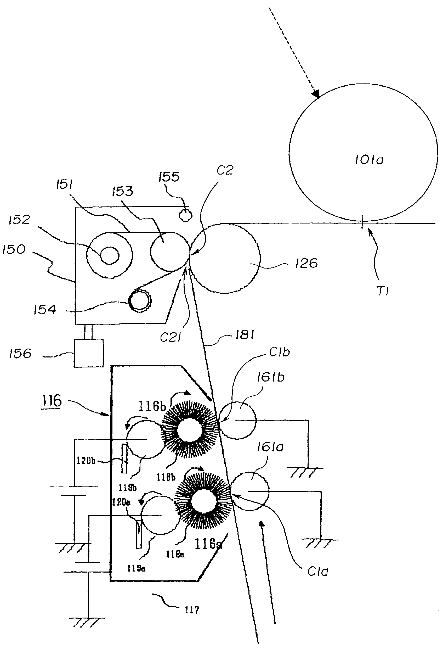
[0040]In FIG. 5, the control of the timing for separating the web 151 from the elastic belt 181 is executed as follows.

[0041]The distance between the central position of the cleaning area C1b of the fur brush 118b and the upstream portion C21 of the cleaning area C2 of the web 151 in the moving direction of the elastic belt 181 is set to 50 mm.

[0042]Likewise, the distance between the upstream portion C21 of the cleaning area C2 of the web 151 and the central position of the primary transfer portion T1 in which the photosensitive drum 101a makes contact with the elastic belt 181 in the moving direction of the elastic belt 181 is set to 97 mm. The distance from an exposure position on the photosensitive drum 101a to the center of the primary transfer portion T1 in the rotating direction of the photosensitive drum 101a is set to 117 mm. The circumferential velocity of the photosensitive drum 101a and the elastic belt 181 is set to 300 mm / sec.

[0043]The time in which the surface of the p...

example 2

[0049]Although in this example, the separation timing of the web 151 is the same as the first embodiment, the web 151 is wound up when the web is separated, so that a new web face makes contact with the elastic belt 181. As a consequence, an amount of time in which the image formation is interrupted by the winding activity of the web 151 can be reduced.

Web Control

example 3

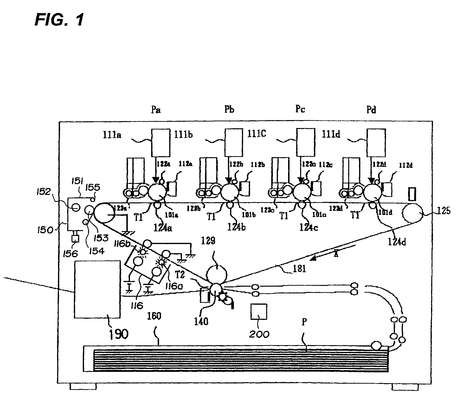
[0050]In the above-described examples 1 and 2, the web 151 is separated based on a writing signal of the image area front end. In this example, the rear end of the sheet P is detected with a sheet detection sensor 200 disposed on the upstream side of the secondary transfer portion T2 in the moving direction of the sheet.

[0051]The web 151 is kept separated from the elastic belt 181 in a period from when the detection signal of the sheet detecting sensor 200 is outputted to when the front end of a next image comes. The same effect as the first and second embodiments is obtained.

[0052]The respective units which constitute the image forming portion Pa will be described here.

[0053]The photosensitive drum 101a is constructed by coating the outer peripheral face of aluminum cylinder with an organic photoconductive layer (OPC). The photosensitive drum 101a is supported rotatably by a flange at both end portions and an end portion thereof receives a rotation force from a drive motor (not sho...


PUM


Abstract

The image forming apparatus of this invention includes an image bearing member which bears a toner image; a toner image forming device which forms a plurality of the toner images on the image bearing member continuously; a transfer device which transfers the toner image on the image bearing member to a recording material; a cleaning web which wipes off toner remaining on the image bearing member after the toner image is transferred to the recording material; and a separating unit which separates the web from the image bearing member when the toner image forming means is forming a plurality of the toner images on the image bearing member continuously.

Description

BACKGROUND OF THE INVENTION[0001]1. Field of the Invention[0002]The present invention relates to an image forming apparatus using an electrophotographic system and more particularly to an image forming apparatus having a member for wiping off toner on an intermediate transfer member.[0003]2. Description of the Related Art[0004]An image forming apparatus for forming an image on a recording material using an electrophotographic system employs a method of transferring an image transferred once to an intermediate transfer member to a recording material in order to form a high quality image corresponding to a variety of the recording materials in terms of size and material.[0005]As a method for removing toner left on the intermediate transfer member after the toner image is transferred to the recording material, a method of bringing a blade shaped member into a contact with the intermediate member by applying pressure and a method of bringing a brush member applied with a voltage into a ...

Claims


Application Information

Patent Timeline
Patent Type & Authority Patents(United States)
IPC IPC(8): G03G15/16G03G21/00
CPCG03G15/161
Inventor TAKISHITA, SHIGEKI
Owner CANON KK
Why Eureka
Try Eureka