Image forming apparatus

Inactive Publication Date: 2007-10-04
CANON KK
View PDF8 Cites 13 Cited by
  • Summary
  • Abstract
  • Description
  • Claims
  • Application Information

AI Technical Summary

Benefits of technology

[0008]An object of the present invention is to prevent occurrence of cleaning failure in an image

Problems solved by technology

However, sometimes the above-mentioned methods cannot remove small-particle substance such as additive contained

Method used


Image

  • Image forming apparatus
  • Image forming apparatus
  • Image forming apparatus

Examples


Embodiment Construction

[0015]Hereinafter, an exemplary embodiment of the image forming apparatus of the present invention will be described in detail with reference to the accompanying drawings.

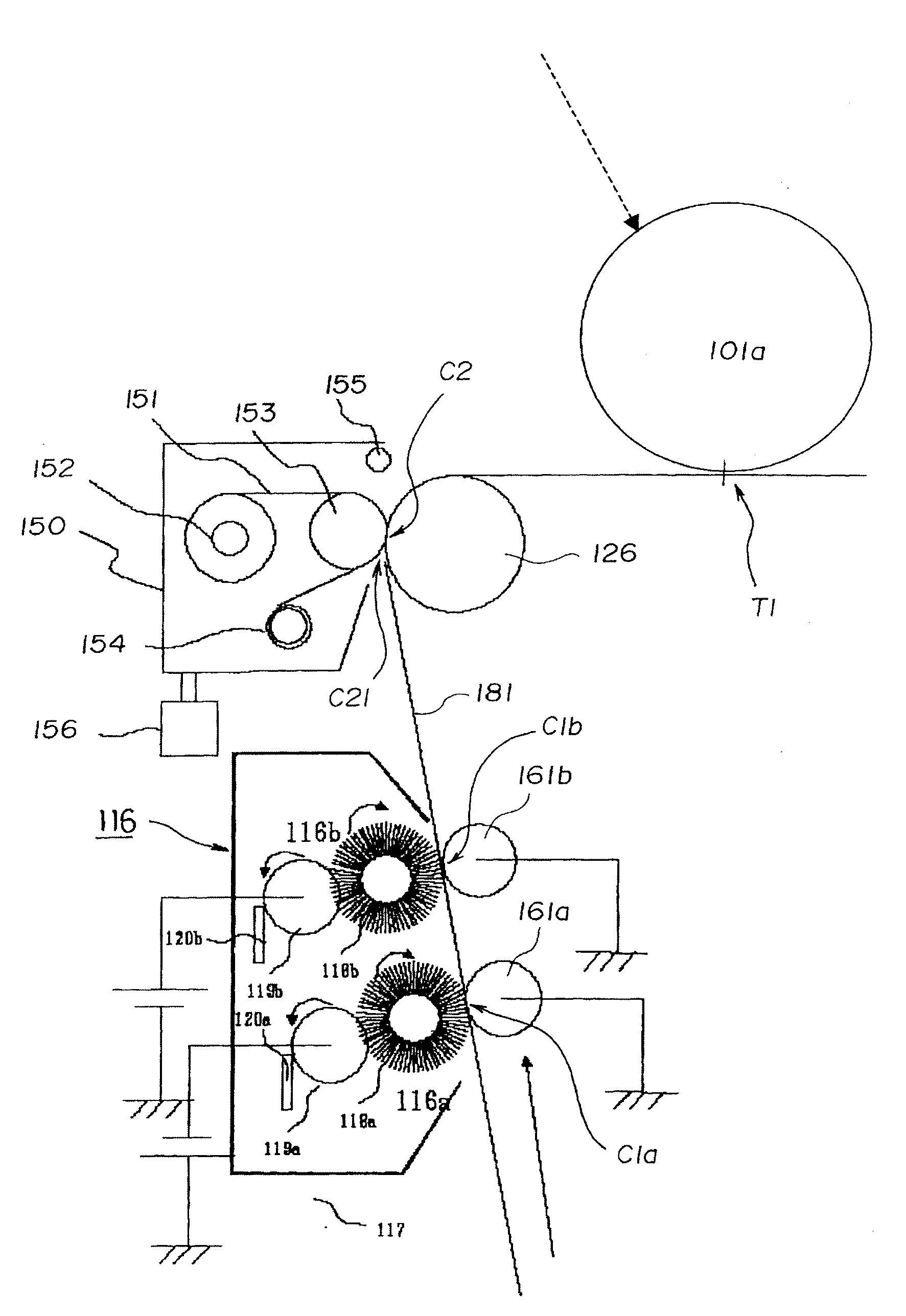
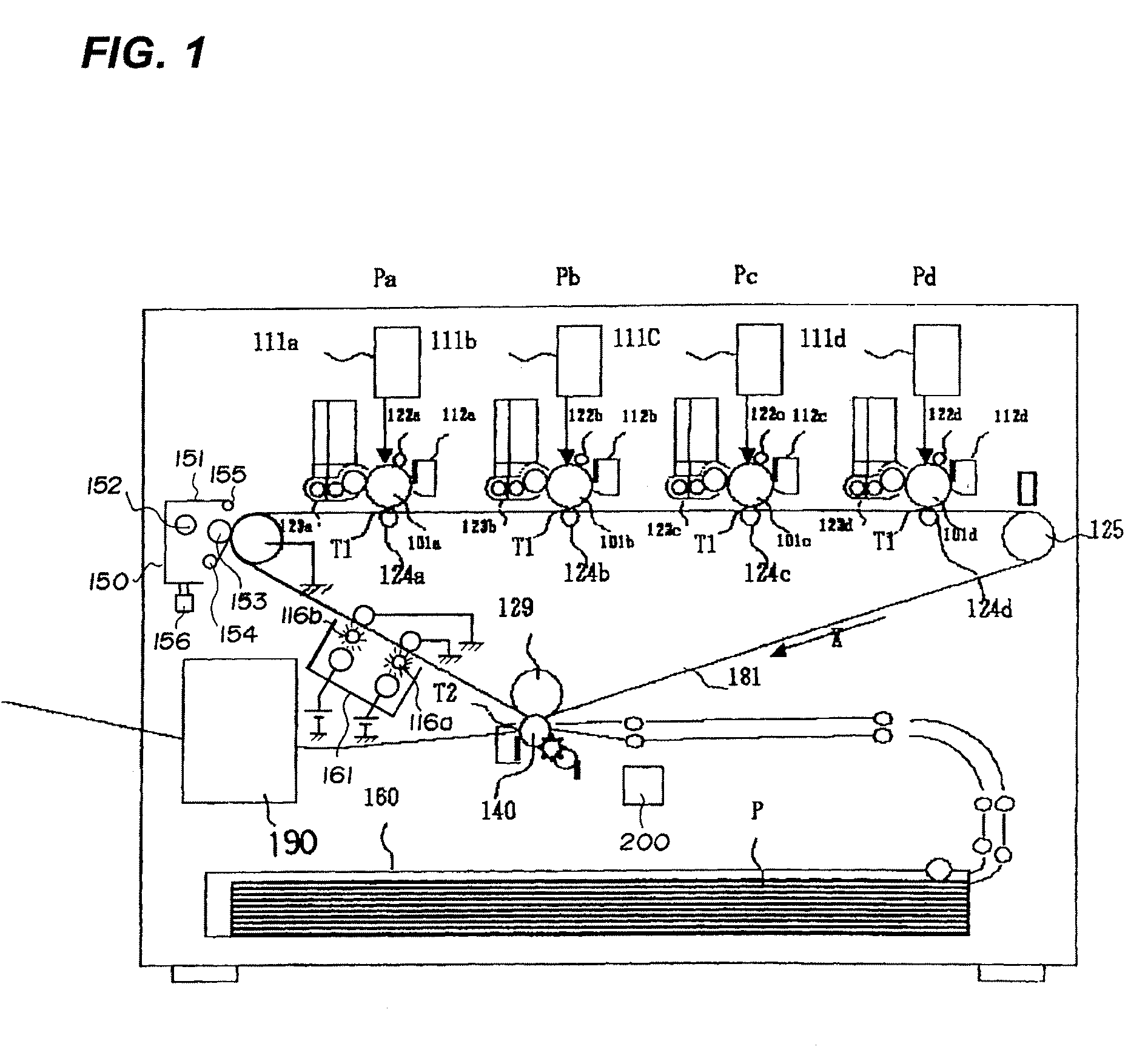
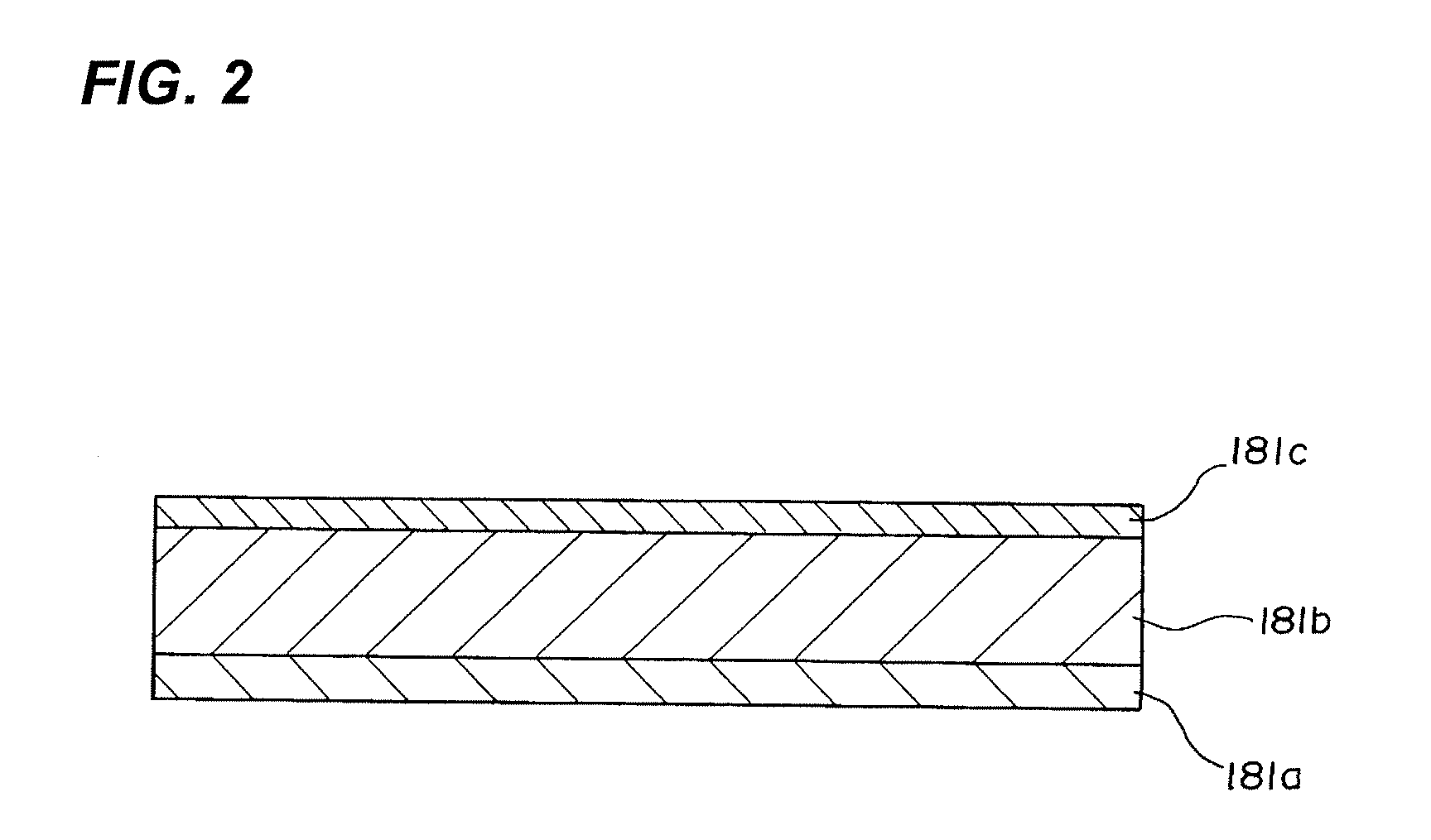
[0016]FIG. 1 shows a tandem type image forming apparatus having four photosensitive drums as electrostatic latent image bearing members corresponding to four colors, yellow (Y), magenta (M), cyan (C) and black (K). An endless elastic belt (image bearing member) 181 which is an intermediate transfer member equipped on this apparatus main body is stretched between a drive roller 125, a tension roller 126 and a backup roller 129. Using the elastic belt 181 as the intermediate transfer member enables reducing so-called hollow defects that part of the toner image is left on the intermediate transfer member when the toner image on the intermediate transfer member is transferred to a recording material. As shown in FIG. 2, the elastic belt 181 is constituted of three-layer lamination of resin layer 181a, elastic layer 181...


PUM


Abstract

The image forming apparatus of this invention comprises: an image bearing member which bears a toner image; a toner image forming means which forms a plurality of the toner images on the image bearing member continuously; a transfer means which transfers the toner image on the image bearing member to a recording material; a cleaning web which wipes off toner remaining on the image bearing member after the toner image is transferred to the recording material; and a separating unit which separates the image bearing member cleaning member from the image bearing member when the toner image forming means is forming a plurality of the toner images on the image bearing member continuously.

Description

BACKGROUND OF THE INVENTION[0001]1. Field of the Invention[0002]The present invention relates to an image forming apparatus using electrophotographic system and more particularly to an image forming apparatus having a member for wiping off toner on an intermediate transfer member.[0003]2. Description of the Related Art[0004]The image forming apparatus for forming an image on a recording material using electrophotographic system employs a method of transferring an image transferred once to an intermediate transfer member to a recording material in order to form a high quality image corresponding to a variety of the recording materials in terms of size and material.[0005]As a method for removing toner left on the intermediate transfer member after the toner image is transferred to the recording material, a method of bringing a blade shaped member into a contact with the intermediate member by applying pressure and a method of bringing a brush member applied with a voltage into a conta...

Claims


Application Information

Patent Timeline
IPC IPC(8): G03G15/16
CPCG03G15/161
Inventor TAKISHITA, SHIGEKI
Owner CANON KK
Why Eureka
Try Eureka