Connected hot-water supply system

Active Publication Date: 2016-06-30
RINNAI CORP
View PDF6 Cites 1 Cited by
  • Summary
  • Abstract
  • Description
  • Claims
  • Application Information

AI Technical Summary

Benefits of technology

The present invention provides a connected hot-water supply system that includes multiple hot-water suppliers that are connected to each other. The system includes a hot-water supply controller for each hot-water supplier that controls the hot-water supply operation. Each hot-water supplier has a fan to create airflow for combustion. Combustion exhaust is collected from each hot-water supplier through a common exhaust passage. The hot-water supply controllers communicate with a connection control unit to synchronize the operation of the hot-water suppliers. The combustion regulator is responsible for regulating the combustion amount in each hot-water supplier to ensure consistent rotation speed of the fan among the hot-water suppliers. This ensures consistent pressure of the combustion exhaust and prevents combustion failure when using a common vent system.

Problems solved by technology

However, since a plurality of exhaust ducts of the respective hot-water suppliers are connected to a single common exhaust duct in the common vent system, a difference in pressure of the combustion exhaust among the respective exhaust ducts, if generated, may exert an adverse influence on the combustion of the respective hot-water suppliers.
Accordingly, if, for example, the combustion amount of one hot-water supplier becomes smaller than that of other hot-water suppliers while all the hot-water suppliers that constitute the connected hot-water supply system are in hot-water supply operation, the rotation speed of the fan that feeds combustion air to the burner in accordance with the combustion amount is dropped in that one hot-water supplier, which results in a drop in the pressure of combustion exhaust.
In the hot-water supplier where the pressure of combustion exhaust is dropped, smooth exhausting operation is hindered due to a relatively high pressure of the combustion exhaust from other hot-water suppliers, which may increase exhalation resistance and cause combustion failure of the burner.

Method used


Image

  • Connected hot-water supply system
  • Connected hot-water supply system
  • Connected hot-water supply system

Examples


Embodiment Construction

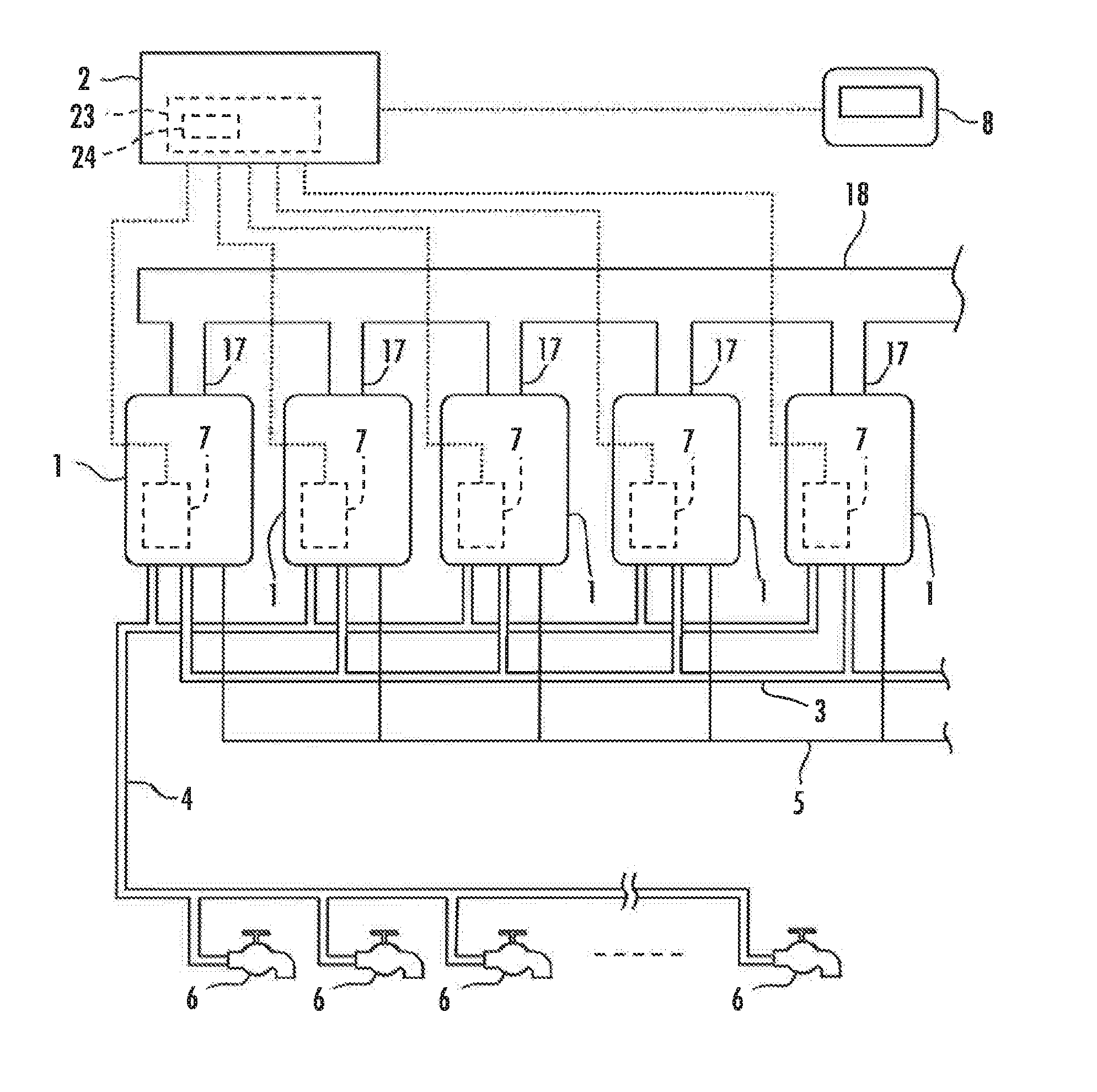
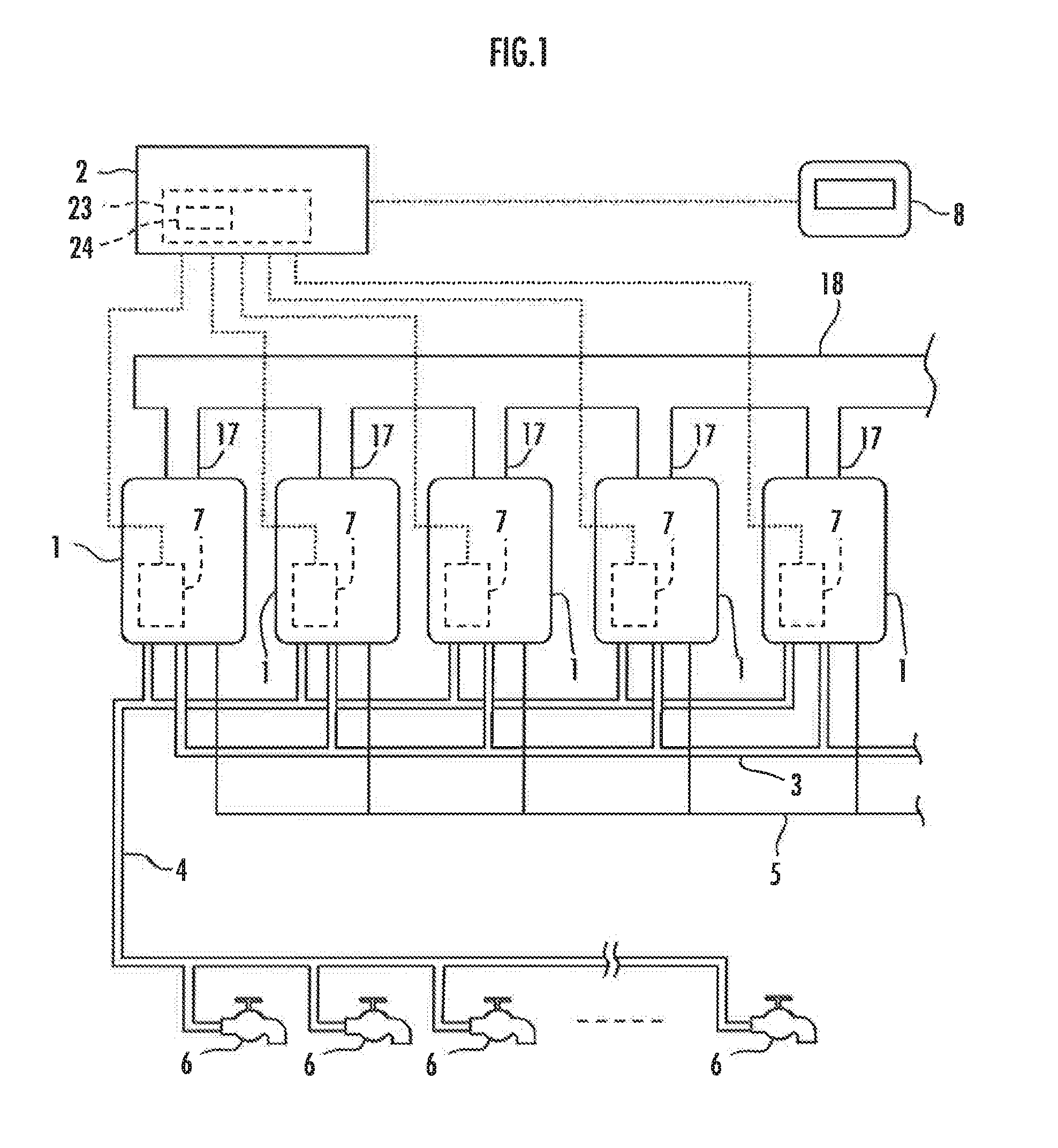
[0024]An embodiment of the present invention will be described hereinbelow with reference to the accompanying drawings. As illustrated in FIG. 1, a connected hot-water supply system in the embodiment of the present invention comprises a plurality of hot-water suppliers 1, a connection control unit 2 (connection control unit) configured to control each of the hot-water suppliers 1, a water pipe 3 configured to supply water to each of the hot-water suppliers 1, a hot-water pipe 4 configured to deliver hot water from each of the hot-water suppliers 1, and a gas supply pipe 5 configured to supply gas to each of the hot-water suppliers 1. The hot-water pipe 4 is connected to a plurality of faucets 6.

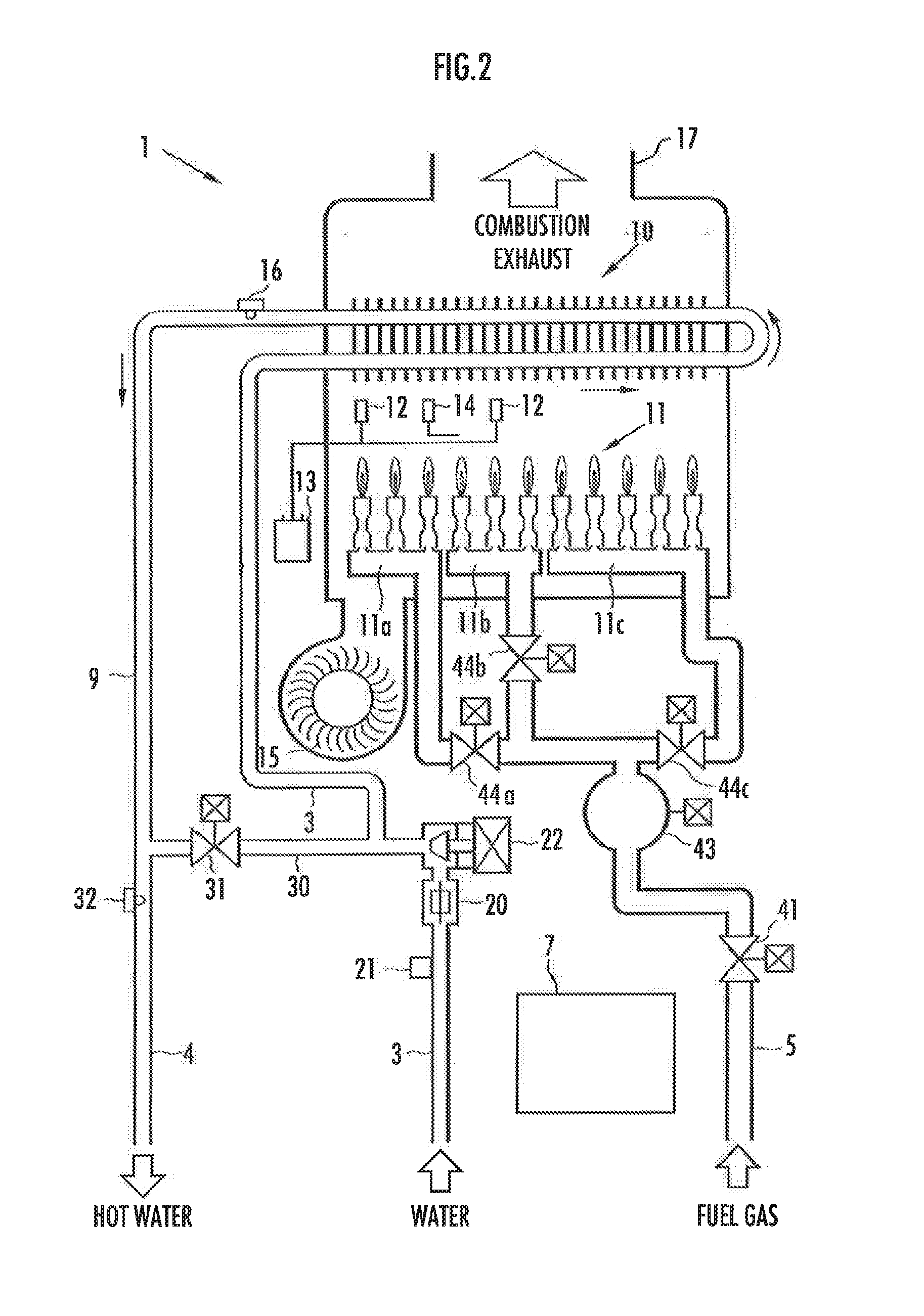
[0025]The hot-water supplier 1 is equipped with a hot-water supply controller 7 that is an electronic unit constituted by a microcomputer and the like. The connection control unit 2 is equipped with a remote controller 8 configured to operate the hot-water supply temperature of the connected ...


PUM


Abstract

To provide a connected hot-water supply system capable of preventing combustion failure of the burner of each hot-water supplier during hot-water supply operation to achieve stable hot-water supply operation. When dispersion in the rotation speed of a fan 15 among respective hot-water suppliers 1 is detected, a connection control unit 2 regulates the combustion amount of each of the hot-water suppliers 1 so as to reduce a difference in the rotation speed of the fan 15 among the respective hot-water suppliers 1.

Description

BACKGROUND OF THE INVENTION[0001]1. Field of the Invention[0002]The present invention relates to a connected hot-water supply system including a connection control unit connected to a plurality of hot-water suppliers to control operation of the respective hot-water suppliers.[0003]2. Description of the Related Art[0004]Connected hot-water supply systems that use a plurality of hot-water suppliers in accordance with required hot-water supply capacity have conventionally been known (see, for example, Japanese Laid-open Patent Publication No. 2011-158138). The connected hot-water supply systems of this type, unlike large-size hot-water suppliers that are custom-designed at high cost, can be installed by connecting a plurality of general-purpose low-cost hot-water suppliers in accordance with required hot-water supply capacity. Therefore, the connected hot-water supply systems can reduce the cost of hot-water supply equipment.[0005]When the hot-water suppliers which constitute a connect...

Claims


Application Information

Patent Timeline
IPC IPC(8): F24H9/20F24H9/12F23N3/08F24H1/20
CPCF24H9/2085F24H1/20F23N2041/04F23N3/082F24H9/124F23N2241/04F24H9/133F24H15/219F24H15/238F24H15/174F24H15/215F24H15/36F24H15/325F24H15/31F24H9/2035F24H15/35F24H15/45
Inventor SATO, ERIKITAGAWA, HIDEKI
Owner RINNAI CORP
Why Eureka
Try Eureka