Wire electrical discharge machine and electrical discharge machining method

Active Publication Date: 2020-04-23
FANUC LTD
View PDF0 Cites 0 Cited by
  • Summary
  • Abstract
  • Description
  • Claims
  • Application Information

AI Technical Summary

Benefits of technology

The present invention aims to prevent failures during electrical discharge machining caused by fluctuations in gap voltage caused by a capacitor. The technical effect is the prevention of improper machining due to such fluctuations.

Problems solved by technology

However, when a capacitor is included in the power circuit that applies a spark inducing voltage between the electrodes, the capacitor sometimes may build up electric charge due to the supply of the machining current between the electrodes.
The built up charge will cause gap voltage fluctuation, resulting in failure to perform appropriate machining.

Method used


Image

  • Wire electrical discharge machine and electrical discharge machining method
  • Wire electrical discharge machine and electrical discharge machining method
  • Wire electrical discharge machine and electrical discharge machining method

Examples


embodiment

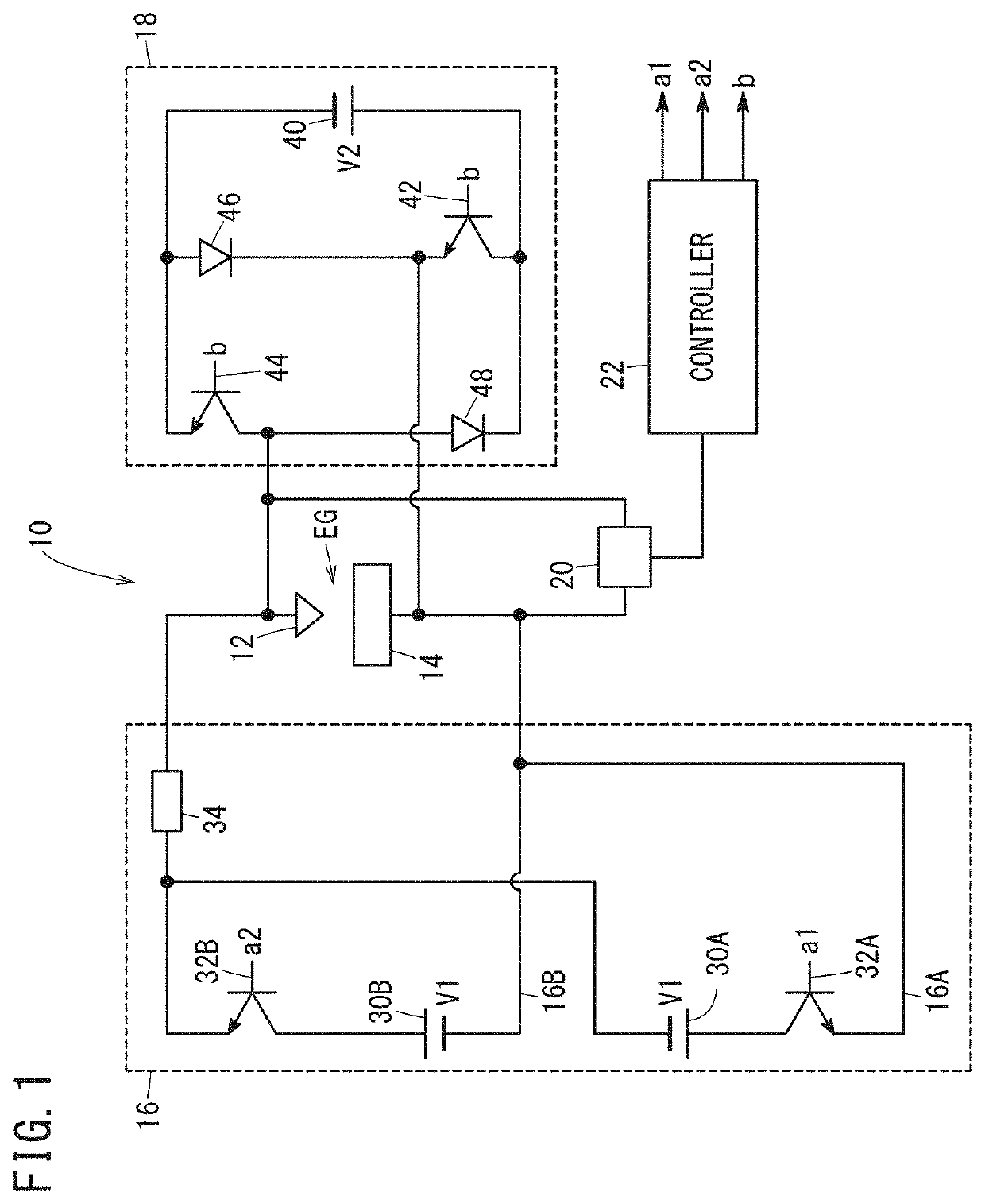
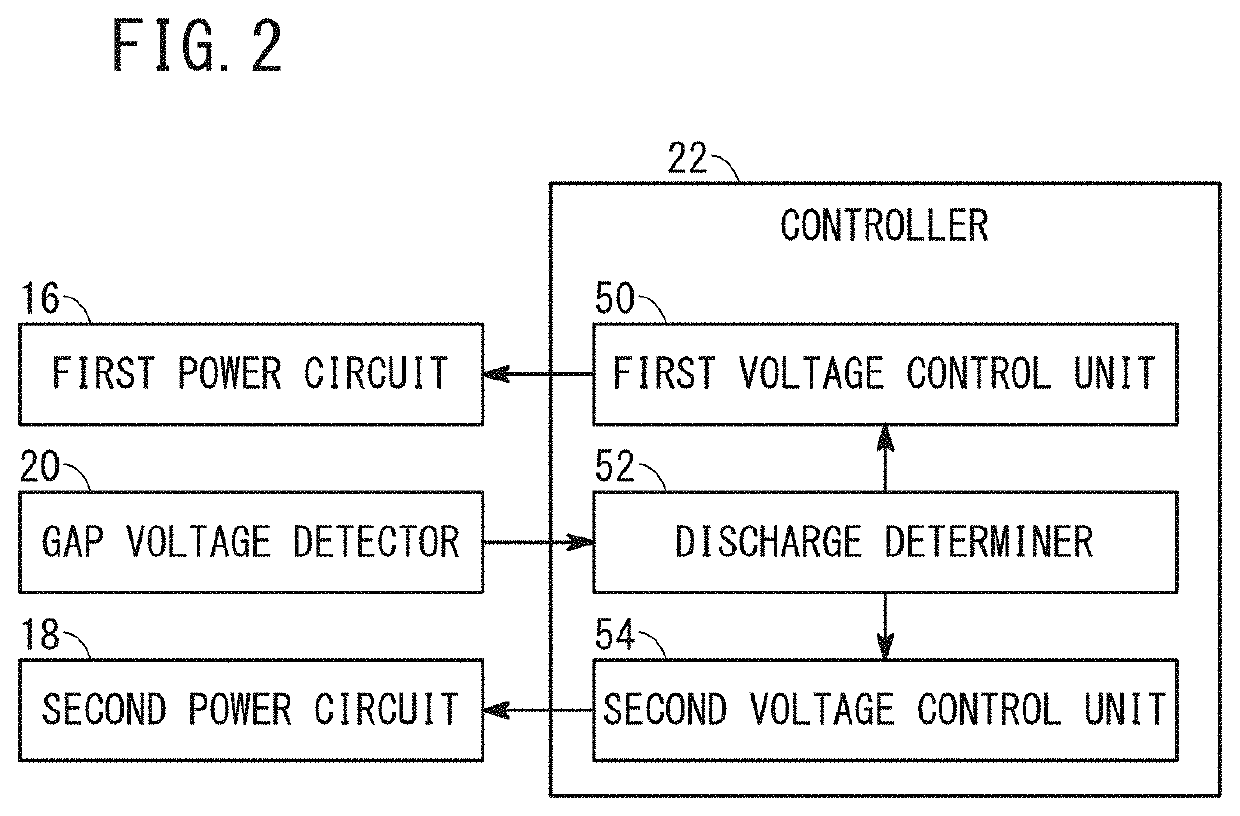
[0016]FIG. 1 is a diagram illustrating a schematic circuit configuration of a wire electrical discharge machine 10 according to the present embodiment. The wire electrical discharge machine 10 is an apparatus for machining a workpiece 14 by applying voltage across an electrode gap EG formed between a wire electrode 12 and the workpiece 14 to generate electrical discharge. The wire electrical discharge machine 10 sends out the wire electrode 12, changes the relative position of the wire electrode 12 to the workpiece 14 to machine the workpiece 14 into a desired shape. The wire electrical discharge machine 10 includes the wire electrode 12, a first power circuit 16, a second power circuit 18, a gap voltage detector 20, a controller 22 and the like.

[0017]The first power circuit 16 induces electric discharge by applying a first voltage V1 across the electrode gap EG. The first power circuit 16 includes a positive polarity circuit 16A that applies a first voltage V1 of positive polarity ...


PUM

PropertyMeasurementUnit
Currentaaaaaaaaaa
Electric potential / voltageaaaaaaaaaa

Abstract

A wire electrical discharge machine includes: a gap voltage detector for detecting a voltage across an electrode gap; a first voltage control unit for applying a first voltage to the electrode gap; a discharge determiner for determining whether or not the electrode gap is in a discharging state during application of the first voltage; and a second voltage control unit for supplying a machining current through the electrode gap when the electrode gap is in a discharging state. After a supply of the machining current to the electrode gap, even when a discharge is induced by the next application of the first voltage to the electrode gap, the second voltage control unit prohibits application of a second voltage to the electrode gap.

Description

CROSS-REFERENCE TO RELATED APPLICATION[0001]This application is based upon and claims the benefit of priority from Japanese Patent Application No. 2018-199279 filed on Oct. 23, 2018, the contents of which are incorporated herein by reference.BACKGROUND OF THE INVENTIONField of the Invention[0002]The present invention relates to a wire electrical discharge machine and an electrical discharge machining method that perform electrical discharge machining on a workpiece by applying voltage across the electrode gap between a wire electrode and the workpiece to generate electrical discharge.Description of the Related Art[0003]As disclosed in Japanese Laid-Open Patent Publication No. 2016-196078, in the wire electrical discharge machining technology, a voltage (spark inducing voltage) for inducing electrical discharge is applied across the electrode gap between the wire electrode and the workpiece, and when a discharge is generated, a machining current (discharge current) is supplied betwee...

Claims


Application Information

Patent Timeline
IPC IPC(8): B23H1/02B23H7/04B23H7/18B23H7/08
CPCB23H7/18B23H1/024B23H7/08B23H1/022B23H7/04B23H1/00B23H11/00B23H7/02B23H7/14
Inventor HASEGAWA, YASUO
Owner FANUC LTD
Why Eureka
Try Eureka