Electrically driven stapler

Active Publication Date: 2006-07-20
MAX CO LTD
View PDF11 Cites 7 Cited by
  • Summary
  • Abstract
  • Description
  • Claims
  • Application Information

AI Technical Summary

Benefits of technology

[0009] According to the present invention, the magazine is supported by the support frame being capable of moving, the cam follower is formed on the side of the magazine being protruded, and when this cam follower is engaged with the cam groove formed in the drive rotary member for driving the staple drive mechanism arranged on the outer side of the support frame, the magazine can be directly operated by the drive rotary member. Therefore, even when a sliding resistance of the magazine with the support frame supporting the magazine is increased, the magazine is operated in such a manner that the sheets of paper to be stapled are clamped between the magazine and the clincher mechanism before the staple in the magazine is driven. Therefore, it is possible to prevent the occurrence of failure of stapling in which buckling is caused in the staple when the staple is driven out from the magazine before the sheets of paper to be stapled are clamped.

Problems solved by technology

Therefore, when the rotary resistance of the magazine is increased by the abrasion and deformation caused while the electric stapler is being used, it becomes difficult for the magazine to be rotated and the staple is driven out from the magazine section to the sheets of paper to be stapled by the driver plate before the lower face of the magazine is tightly contacted with the sheets of paper to be stapled.
Therefore, buckling is generated in the staple legs and failure in stapling is caused.
Therefore, the forming plate and the driver plate must be operated overcoming the spring force of this high value, which increases a load given to the drive motor.
Accordingly, a large drive motor is required and a drive current to drive the motor is increased, which makes it impossible to save electric power.

Method used


Image

  • Electrically driven stapler
  • Electrically driven stapler
  • Electrically driven stapler

Examples


Embodiment Construction

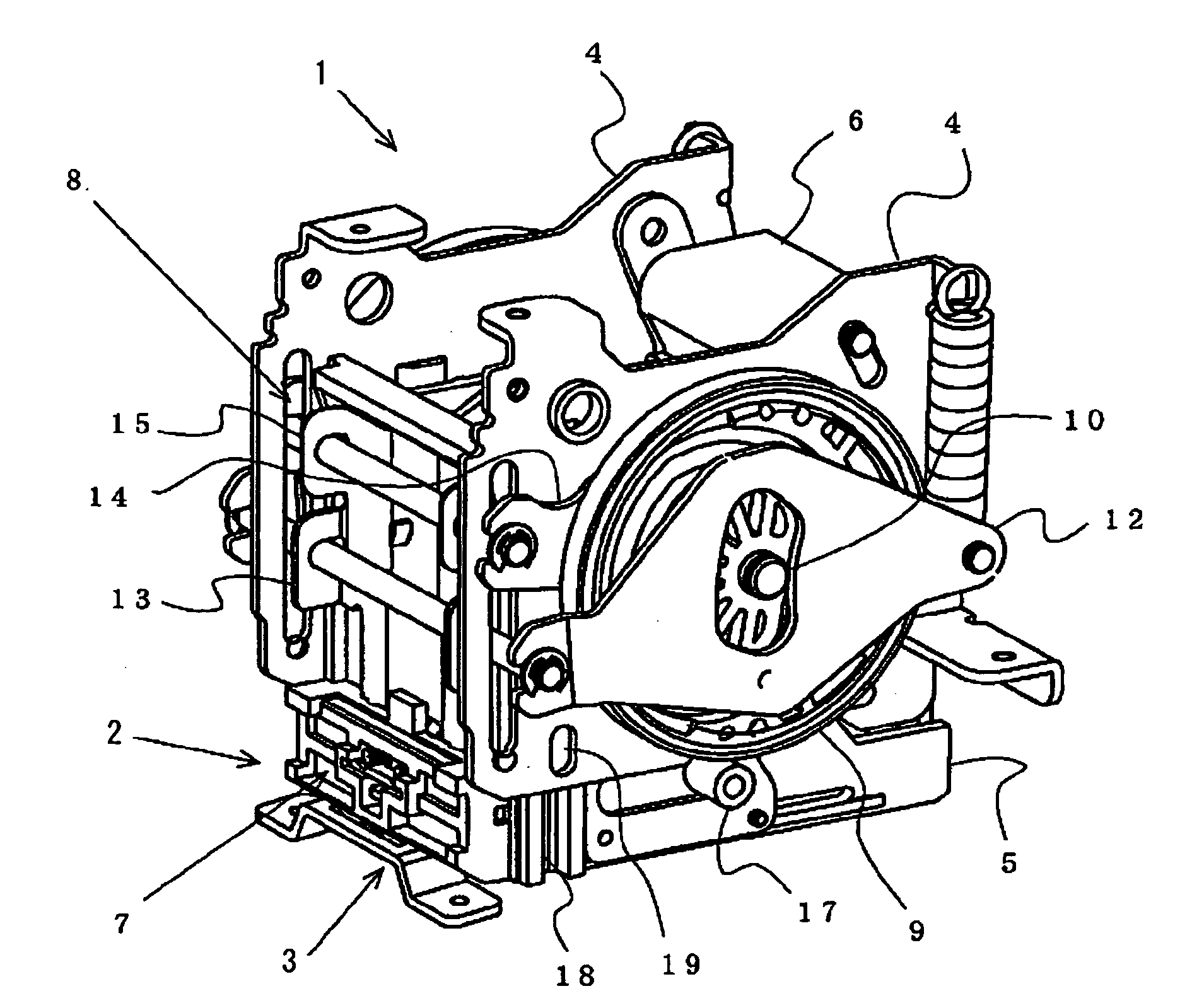
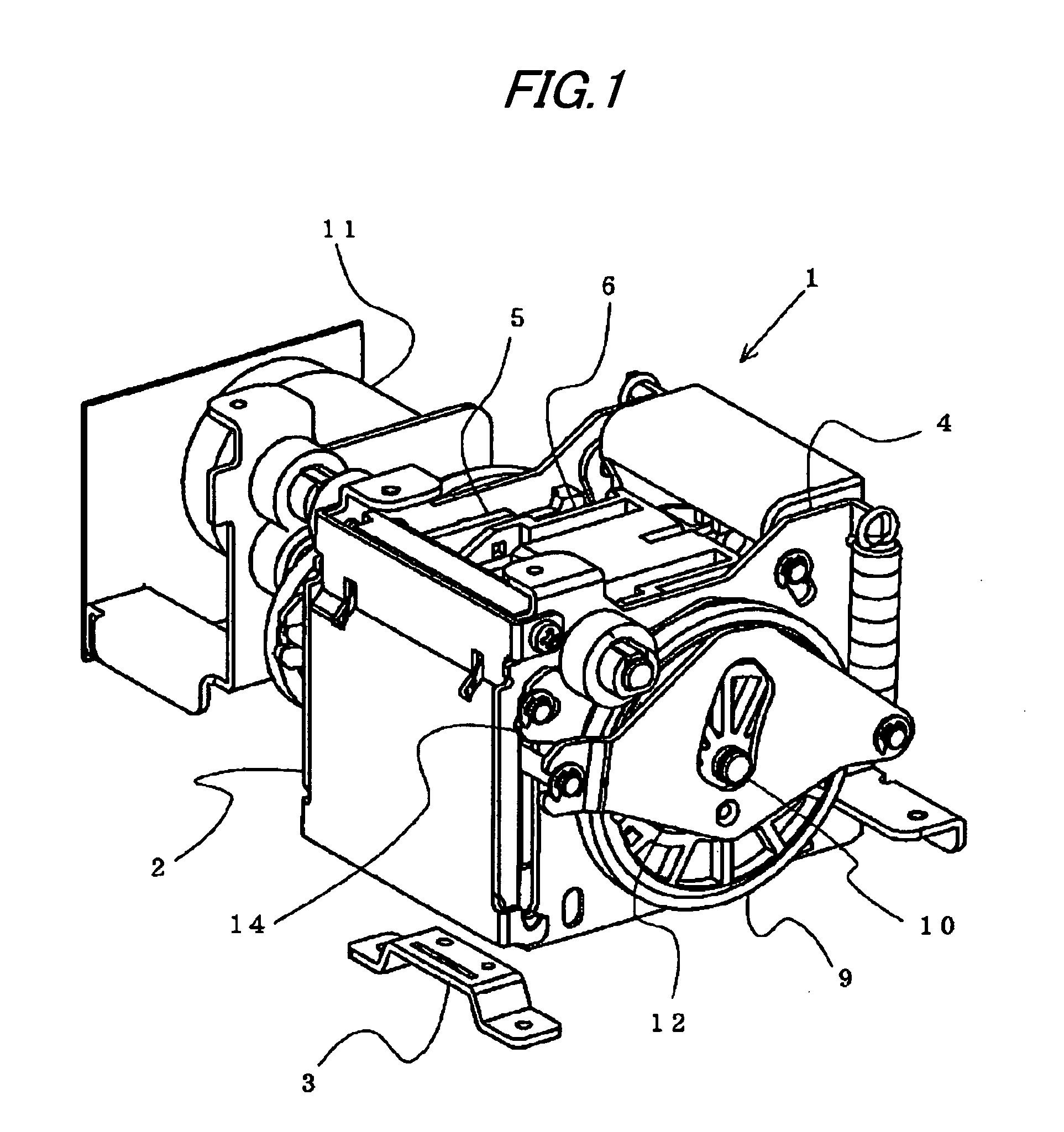
[0020]FIG. 1 is a perspective view showing an entire electric stapler to which the staple supply mechanism of the present invention is applied. The electric stapler 1 is arranged in a conveyance passage for conveying sheets of paper provided in a copier, a printer and so forth. The electric stapler 1 staples a plurality of sheets of paper on which copying or printing has been conducted. In this embodiment, the electric stapler 1 includes: a staple drive section 2 in which the connected staples, formed in such a manner that a large number of straight staple materials are arranged in parallel with each other and the adjoining staple materials are bonded and connected to each other by adhesive so as to be formed into a sheet shape, are supplied to a drive section having an anvil for forming and also having a drive passage for guiding the staple to be driven, and a straight staple material of the lead portion of the connected staples is formed into a U-shape and the thus formed U-shaped...


PUM


Abstract

A magazine 5 attached with a cartridge 6, in which connected staples are charged, is supported inside a support frame 4 being capable of moving toward a clincher section 3. A cam follower 17 is formed being protruded from aside of the magazine 5. When this cam follower 17 is engaged with a cam groove 21 formed in a drive rotary member 9 for driving a staple drive mechanism 8 arranged in the support frame 4, the magazine 5 is directly operated toward the clincher section 3 by the drive rotary member 9.

Description

TECHNICAL FIELD [0001] The present invention relates to an electric stapler in which a cartridge charged with connected staples is attached into a magazine of the electric stapler, the connected staples are successively supplied to a drive section formed at the forward end portion of the cartridge, the staples supplied to the drive section are successively driven toward sheets of paper to be stapled, and leg portions of the staple penetrating the sheets of paper to be stapled are bent along a reverse side of the sheets of paper to be staples, so that the sheets of paper to be stapled can be stapled by the staple driven in this way. BACKGROUND ART [0002] The following electric stapler is well known. Connected staples, in which a large number of straight staple materials are aligned and bonded to each other so that they can be formed into a sheet-shape, are charged into an cartridge. The cartridge is attached into a magazine of the electric stapler. The connected staples are successiv...

Claims


Application Information

Patent Timeline
IPC IPC(8): B25C5/02B27F7/38B25C5/04B25C5/15B25C5/16B27F7/21B27F7/36
CPCB27F7/36B25C5/15B27F7/17B27F7/19
Inventor YAGI, NOBUAKI
Owner MAX CO LTD
Why Eureka
Try Eureka