Cleaning device and image forming apparatus using the same

a technology of cleaning device and image forming apparatus, which is applied in the direction of electrographic process apparatus, instruments, optics, etc., can solve the problems of inability to clean correctly, stain on the intermediate transfer belt, residual toner, etc., and achieve the effect of stably producing high-quality images

Inactive Publication Date: 2009-10-22
SHARP KK
View PDF4 Cites 7 Cited by
  • Summary
  • Abstract
  • Description
  • Claims
  • Application Information

AI Technical Summary

Benefits of technology

[0021]According to the third and fourth aspects of the present invention, specifying the first length to be shorter than the second length makes it possible to press the first cleaning portions against the endless belt more strongly than the second cleaning portion.
[0022]According to the fifth aspect of the present invention, even if the endless belt becomes unstable or irregular at both the side edges, the side end part of the cleaning member corresponding to the first supports can be pressed against the endless belt more strongly than the cleaning member corresponding to the second support is. Accordingly, it is possible to uniformly clean the surface of the circulatively traveling endless belt and prevent occurrence of cleaning failure around the side edges of the endless belt. As a result, it is possible to constantly keep the endless belt as an intermediate transfer medium clean, hence provide an image forming apparatus that can stably produce high quality images.

Problems solved by technology

When this transfer mechanism is adopted, there occurs a problem that “fogging toner” that is caused by residual potential other than the toner image, transfers to the intermediate transfer belt, causing stain on the intermediate transfer belt.
As a result, the surface of intermediate transfer belt 161 is warped irregularly, hence there occurs the problem that residual toner, as weaving through the cleaning blade, fails to be cleaned correctly when the surface of intermediate transfer belt 161 is tried to be uniformly cleaned by cleaning member 165a.

Method used


Image

  • Cleaning device and image forming apparatus using the same
  • Cleaning device and image forming apparatus using the same
  • Cleaning device and image forming apparatus using the same

Examples


Embodiment Construction

[0031]The best embodiment of the present invention will hereinafter be described in detail with reference to the accompanying drawings.

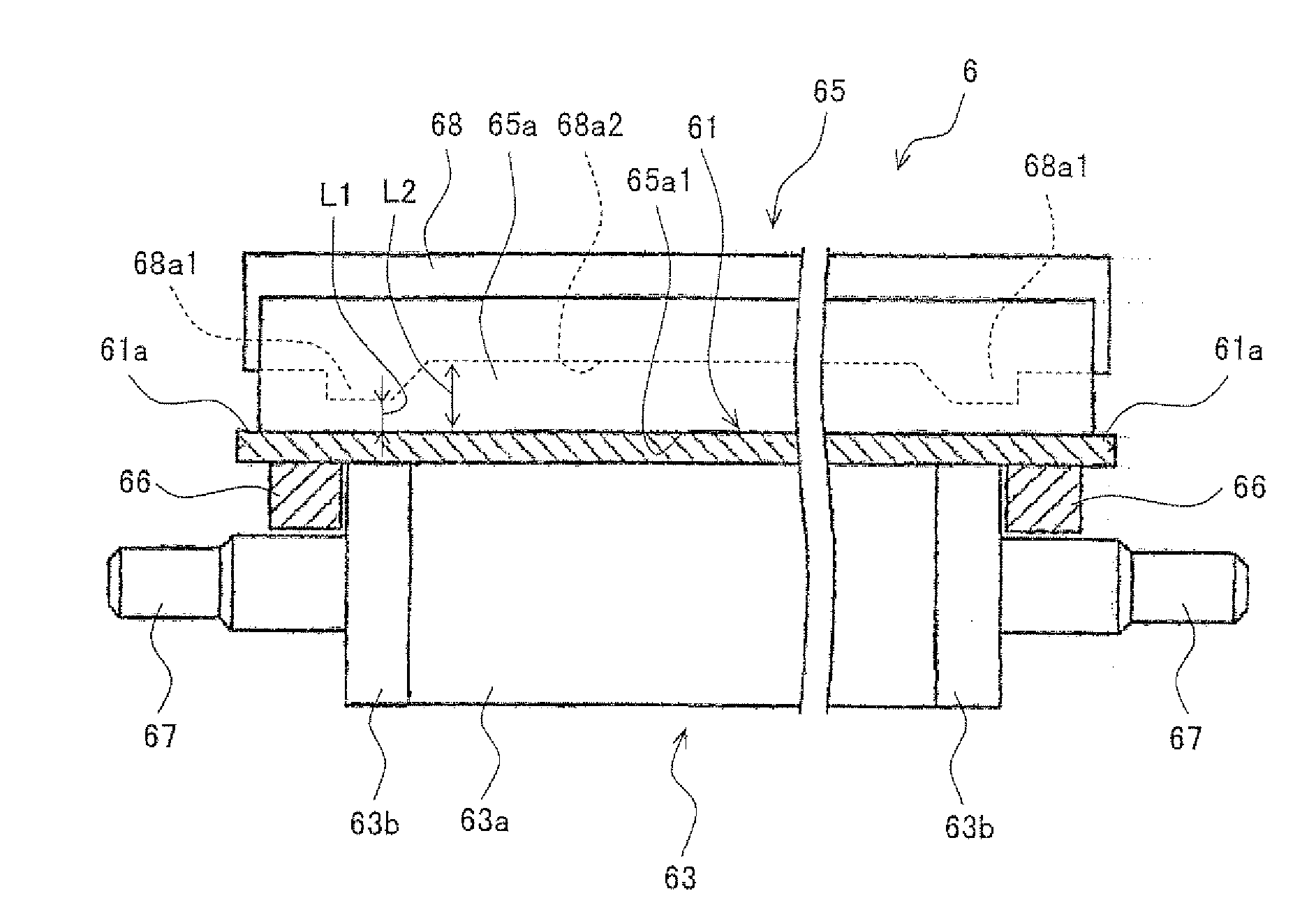
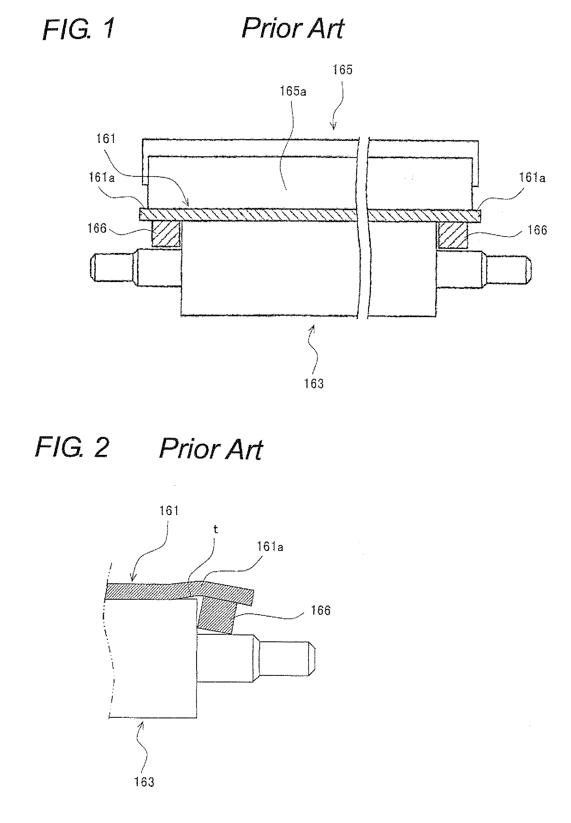
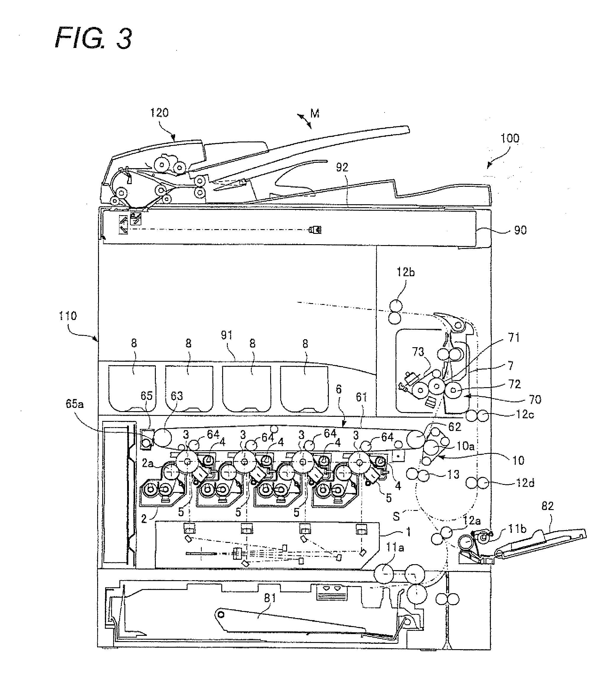
[0032]FIG. 3 is an illustrative view showing an overall configuration of an image forming apparatus in which a cleaning device according to the embodiment of the present invention is adopted. FIG. 4 is an overall view showing a configuration of an intermediate transfer device as a part of the image forming apparatus. In FIG. 4, the arrow designated at B shows a vertical direction (the direction of the gravitational force) and the arrow designated at A shows a horizontal direction.

[0033]An image forming apparatus 100 of the present embodiment includes: as shown in FIGS. 3 and 4, photoreceptor drums 3 on which electrostatic latent images are formed and toner images are formed based on the electrostatic latent images; developing units 2 including developing rollers 2a (FIG. 3) for supplying toner to photoreceptor drums 3; an intermediate transfer device...


PUM


Abstract

An intermediate transfer belt cleaning unit includes a cleaning blade put in sliding contact with the surface of a circulating intermediate transfer belt and a blade holder for holding the blade, the cleaning blade having a length extending across the width of the intermediate transfer belt, the blade holder being formed along the full length of the cleaning blade, for cleaning the surface of the intermediate transfer belt by means of the cleaning blade. In this cleaning unit, the contact pressure of the cleaning blade against the intermediate transfer belt is adjusted so that the contact pressure around both the side edges of the intermediate transfer belt is higher than the contact pressure in the remaining part.

Description

[0001]This Nonprovisional application claims priority under 35 U.S.C. §119(a) on Patent Application No. 2008-108933 filed in Japan on 18 Apr. 2008, the entire contents of which are hereby incorporated by reference.BACKGROUND OF THE INVENTION[0002](1) Field of the Invention[0003]The present invention relates to a cleaning device and an image forming apparatus using the cleaning device, in particular, relating to a cleaning device for cleaning the surface of an endless belt that is circulatively conveyed, as well as to an image forming apparatus using this device.[0004](2) Description of the Prior Art[0005]Conventionally, color image forming apparatuses such as copiers, printers, facsimile machines and the like, include a transfer device for transferring a color toner image formed by the image forming portions, to recording paper. As one of known transfer mechanisms of such a transfer device there is an intermediate transfer system in which toner images of different colors formed at t...

Claims


Application Information

Patent Timeline
Patent Type & Authority Applications(United States)
IPC IPC(8): G03G15/16
CPCG03G15/161G03G2215/1661G03G2215/00151
Inventor IZUMI, HIDESHITAKIGUCHI, TOSHIKIYOSHIDA, TAKAHIKO
Owner SHARP KK
Why Eureka
Try Eureka