Ink container, ink jet recording apparatus, ink filling method, and ink filling device

a recording device and ink jet technology, applied in other printing devices, printing, etc., can solve the problems of defective discharge, choking of the nozzle, and leakage of ink from the recording head nozzle, so as to prevent choking and ensure the stability of the ink discharging operation of the recording head

Inactive Publication Date: 2009-12-08
FUJIFILM CORP
View PDF3 Cites 15 Cited by
  • Summary
  • Abstract
  • Description
  • Claims
  • Application Information

AI Technical Summary

Benefits of technology

[0017]Preferably, the ink jet recording apparatus further comprises a device for detecting a remaining amount of ink in the ink container, wherein if the remaining amount of ink is less than a given amount at the ink filling time, the control device executes a first filling mode wherein the ink is sent from the ink supply tank to the ink container after the ink is sucked out of the ink container, whereas if the remaining amount of ink is not less than the given amount at the ink filling time, the control device executes a second filling mode wherein the ink is sent from the ink supply tank to the ink container without the ink residue being sucked out of the ink container.
[0020]Since the ink filling openings are provided in the periphery of the ink outlet, and the ink residue is sucked out through the ink filling opening before injecting the ink into the ink container through the ink filling openings, the ink container is refilled with the ink without generating any air pool at the ink outlet. Therefore, the nozzles are prevented from choking with air bubbles, so the stability of ink discharging operation of the recording head is ensured.

Problems solved by technology

In an ink jet recording apparatus where an ink cartridge is disposed above a recording head, an ink load in the ink cartridge becomes positive to inner pressure of the recording head, which causes a concern that the ink could leak out of the nozzle of the recording head.
The air pools around the ink outlet 124 result in forming air bubbles in the nozzles, which chokes the nozzles and causes defective discharge.

Method used


Image

  • Ink container, ink jet recording apparatus, ink filling method, and ink filling device
  • Ink container, ink jet recording apparatus, ink filling method, and ink filling device
  • Ink container, ink jet recording apparatus, ink filling method, and ink filling device

Examples


Embodiment Construction

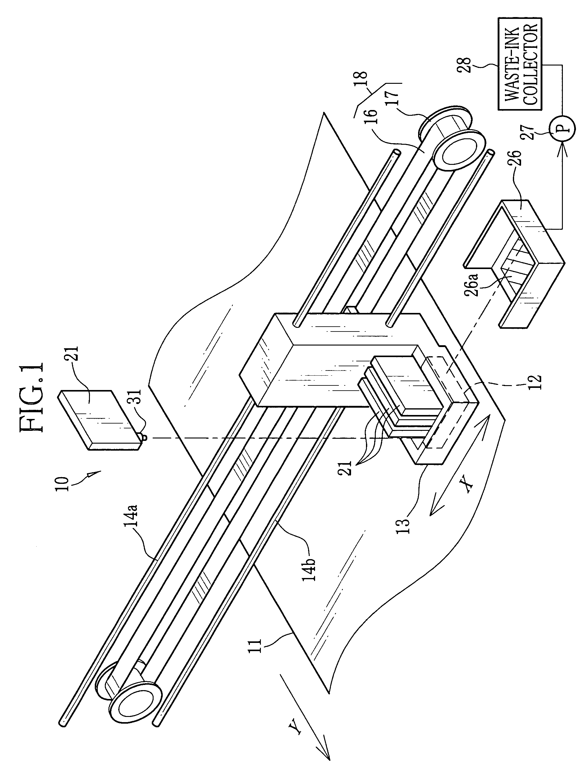
[0034]An ink-jet recording apparatus 10 shown in FIG. 1 is provided with a recording head 12 that discharges ink toward a recording paper 11 to print images thereon. The recording head 12 is provided with a plurality of not-shown nozzles for discharging the ink from individual outlets. The outlets of the nozzles are aligned in a plane to form a discharging surface, and the discharging surface is placed in face to a recording surface of the recording paper 11. The recording head 12 is mounted in a carriage 13 that is movable in a widthwise direction of the recording paper 11, that is, a main scanning direction X. The discharging surface is exposed through an opening formed through a bottom of the carriage 13. While reciprocating in the widthwise direction of the recording paper 11 together with the carriage 13, the recording head 12 records an image in a line sequential fashion. Each time the recording head 12 makes one lap to record a line of the image, the recording paper 11 is fed...


PUM


Abstract

An ink cartridge is formed with an ink outlet, which is connected to an ink jet type recording head through an ink supply path. Ink filling openings are formed around the ink outlet. To refill the ink cartridge with ink, the ink filling openings are connected through an ink filling tube to an ink supply tank. A pump mechanism first reduces pressure inside the ink supply tank, to suck ink residue out of the ink cartridge through the ink filling openings and collect the ink residue into the ink supply tank. Thereafter, the pump mechanism applies pressure to ink in the ink supply tank, to send the ink from the ink supply tank through the ink filling tube and the ink filling openings into the ink cartridge.

Description

FIELD OF THE INVENTION[0001]The present invention relates to an ink container containing ink to be supplied to an ink jet type recording head, an ink jet recording apparatus using the ink container, and a method of and a device for filling the ink container with ink.BACKGROUND OF THE INVENTION[0002]An ink jet recording apparatus has been known, which has a recording head for discharging ink as droplets onto a recording medium to print an image. The ink jet recording apparatus is provided with at least an ink container containing ink, to supply the ink from the ink container to the recording head. In a serial ink jet recording apparatus, a recording head is mounted to a carriage that moves back and forth in a main scanning direction, a widthwise direction of a recording paper. Each time the carriage makes one lap, the recording head records a line of image, and then the recording paper is fed in a sub scanning direction orthogonal to the main scanning direction by an amount correspon...

Claims


Application Information

Patent Timeline
Patent Type & Authority Patents(United States)
IPC IPC(8): B41J29/38B41J2/175B41J2/195
CPCB41J2/17513B41J2/17506
Inventor INOUE, HIROSHI
Owner FUJIFILM CORP
Why Eureka
Try Eureka