Flow Control Device

a flow control and conduit technology, applied in the direction of instruments, sealing/packing, borehole/well accessories, etc., can solve the problems of increasing the ability, increasing the cost of external control and force, and increasing the degree of production, so as to increase the degree of production and production cost

Active Publication Date: 2017-08-17
INFLOWCONTROL
View PDF24 Cites 12 Cited by
  • Summary
  • Abstract
  • Description
  • Claims
  • Application Information

AI Technical Summary

Benefits of technology

The present value of preventing choking and increasing oil production is estimated to be significant, with an estimated increase of at least 10% in production and recovery from a well. The invention's valve is cost-effective compared to the potential increase in oil production.

Problems solved by technology

This is simple and straight-forward technique, but one which provided limited reservoir contact per well.
A major challenge in the production of hydrocarbons from subterranean reservoirs is to increase the ability to recover the oil that is present in the reservoir.
However, the external control and force is expensive, and the number of sections is limited.
However, the external control and force is expensive and the number of zones is limited.
However, they all suffer from the disadvantage that the production is choked also for the oil.
The result is an overall increase in the degree of extraction (recovery) around the wells compared with the traditional ICDs, but with a significant loss of production (barrel / day) during the initial phase of the well's lifetime.
However, a major problem with the solution disclosed in U.S. Pat. No. 7,918,275 B2 is that the valve is in closed position at the time of installation, during which the fluid velocity and friction is zero.
If this problem is solved it would anyway be difficult to control the opening / closing of the valve based on the flow friction since the latter is normally small compared to the friction of the valve mechanisms.
In addition, the functionality of any reversible property based of drag force / friction seems doubtful.

Method used


Image

  • Flow Control Device
  • Flow Control Device
  • Flow Control Device

Examples


Embodiment Construction

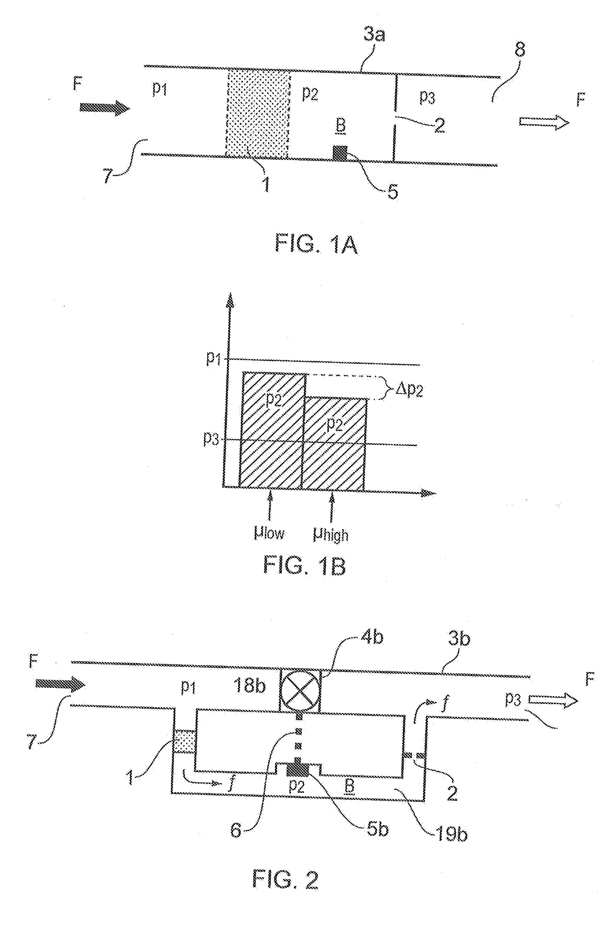
[0063]FIG. 1a illustrates how a fluid F flows into a conduit 3a at a first pressure p1, through a first flow restrictor 1 and into a chamber B where it attains a second pressure p2, and then flows through a second fluid flow restrictor 2 before it exits the conduit 3a at a third pressure p3. When the fluid flow rate and fluid properties (e.g. viscosity, density) are constant, the pressures (p1, p2, p3) are constant, and p1, >p2, >p3.

[0064]In FIG. 1a, the first flow restrictor 1 is a porous element and the second flow restrictor 2 is an orifice.

[0065]In general, the flow characteristics through a porous medium may be described using Darcy's law (i.e. laminar flow), expressed as:

Q=κperm·AμΔPΔL(Equation1)

where: Q=fluid flow rate (units of volume per unit time)[0066]Kperm=relative permeability of the porous medium (typical unit: Darcy)[0067]A=cross-sectional area of the porous medium[0068]μ=viscosity of the fluid (typical unit: centipoise; SI unit: Pa*s)[0069]ΔP=differential fluid press...


PUM


Abstract

A fluid flow control device serving as an inflow port from a fluid reservoir (R) to the interior of a production pipe (S) is in the form of a housing (3b, 3c, 3d, 3e, 3f, 3g, 3h, 3i, 3j, 3k, 3l). The housing has a primary flow path (18) and a secondary flow path (19). The secondary flow path is in fluid communication with a chamber (B) in which is arranged an actuator (5) for a valve device (4), the valve device arranged to open and close the primary flow path. At least one flow restrictor (1,2) is arranged in the secondary flow path, the flow restrictor arranged to provide a pressure to chamber (B) sufficient to actuate the valve to an open position when the fluid flowing through the secondary flow path is oil, and a pressure sufficient to actuate the valve to a closed position when the fluid has a viscosity and / or density less than oil.

Description

CROSS-REFERENCES TO RELATED APPLICATIONS[0001]This application is a Continuation under 35 U.S.C. §120 of application Ser. No. 14 / 386,459, filed 19, Sep. 2014 which is a National Stage application under 35 U.S.C. §371 of PCT / EP2016 / 054485 filed 6, Mar. 2013, which claimed the benefit of U.S. Provisional applications 61 / 679,805 filed 6, Aug. 2012 and 61 / 613,515 filed 21, Mar. 2012.FIELD OF THE INVENTION[0002]The invention concerns the control of fluid flowing into a conduit. More specifically, the invention concerns a device and a method of controlling the flow of fluids having different properties. The invention is useful in controlling flow of fluids from a subterranean hydrocarbon reservoir and into a production string. The invented device and method are useful for production fluids and in the fluid injection context.BACKGROUND OF THE INVENTION[0003]A well for producing hydrocarbons from a subterranean reservoir may extend through the reservoir in a number of orientations. Traditio...

Claims


Application Information

Patent Timeline
Patent Type & Authority Applications(United States)
IPC IPC(8): E21B34/08F16K31/122E21B34/14G05D7/01
CPCE21B34/08E21B34/14F16K31/1221G05D7/0133E21B43/12E21B43/32Y10T137/2562Y10T137/0379Y10T137/3421Y10T137/7851Y10T137/86734Y10T137/7839Y10T137/86718G05D7/01
Inventor MATHIESEN, VIDARWERSWICK, BJORNARAAKRE, HAAVARD
Owner INFLOWCONTROL
Why Eureka
Try Eureka