Eyeglass frame measurement apparatus

a technology for measuring apparatus and eyeglass frames, which is applied in the direction of mechanical measuring arrangements, instruments, and spectacles/goggles, etc., can solve the problem of inability to narrow and achieve the effect of narrowing the measurable vertical width of the frame and stabilizing the eyeglass fram

Active Publication Date: 2009-12-15
NIDEK CO LTD
View PDF17 Cites 12 Cited by
  • Summary
  • Abstract
  • Description
  • Claims
  • Application Information

AI Technical Summary

Benefits of technology

[0007]The invention has been finalized in view of the drawbacks inherent in the known eyeglass frame measurement apparatus, and an object of the invention is to provide an eyeglass frame measurement apparatus that, even if clamp pins are made short in length, is capable of stably holding an eyeglass frame, making a measurable vertical width of a frame narrow, preventing a tracing stylus from interfering with the clamp pins during measurement.

Problems solved by technology

Accordingly, if the length LP of each clamp pin is long, when measurement is made on an eyeglass frame F2 having a rim whose vertical width is small, the tracing stylus interferes with the clamp pins, and as a result, it is impossible to narrow the measurable vertical width of the frame.

Method used


Image

  • Eyeglass frame measurement apparatus
  • Eyeglass frame measurement apparatus
  • Eyeglass frame measurement apparatus

Examples


Embodiment Construction

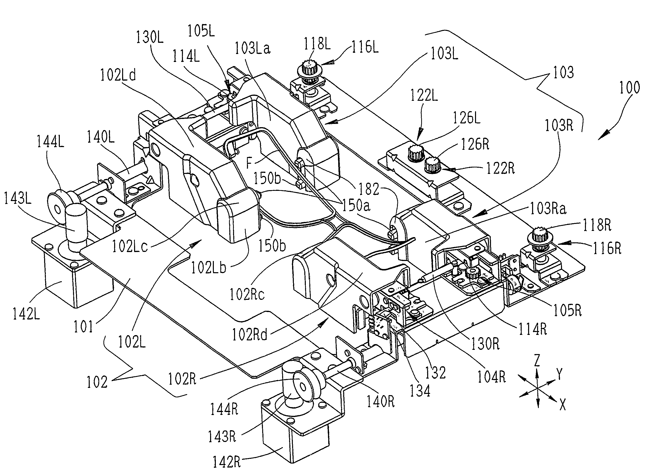
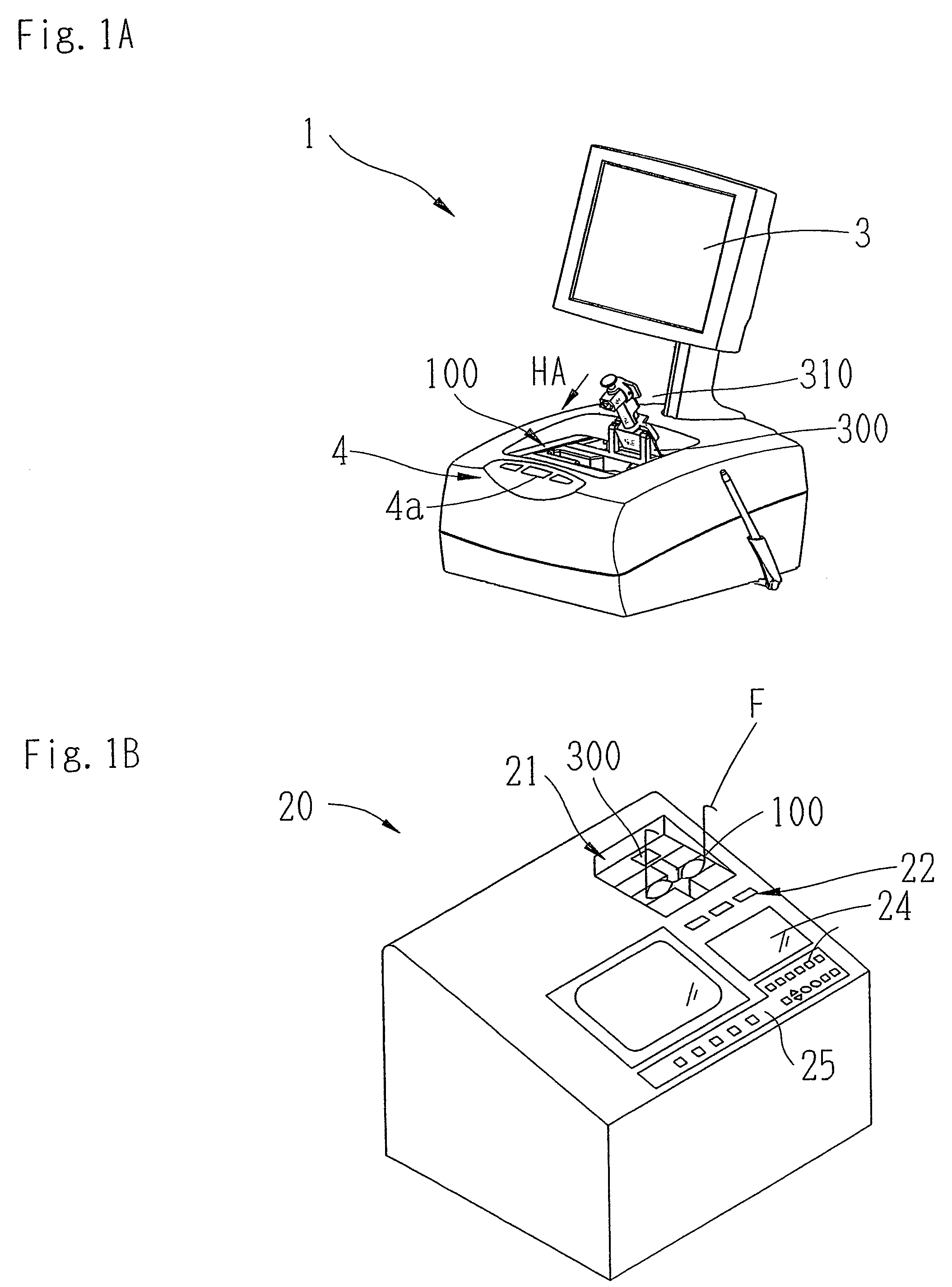
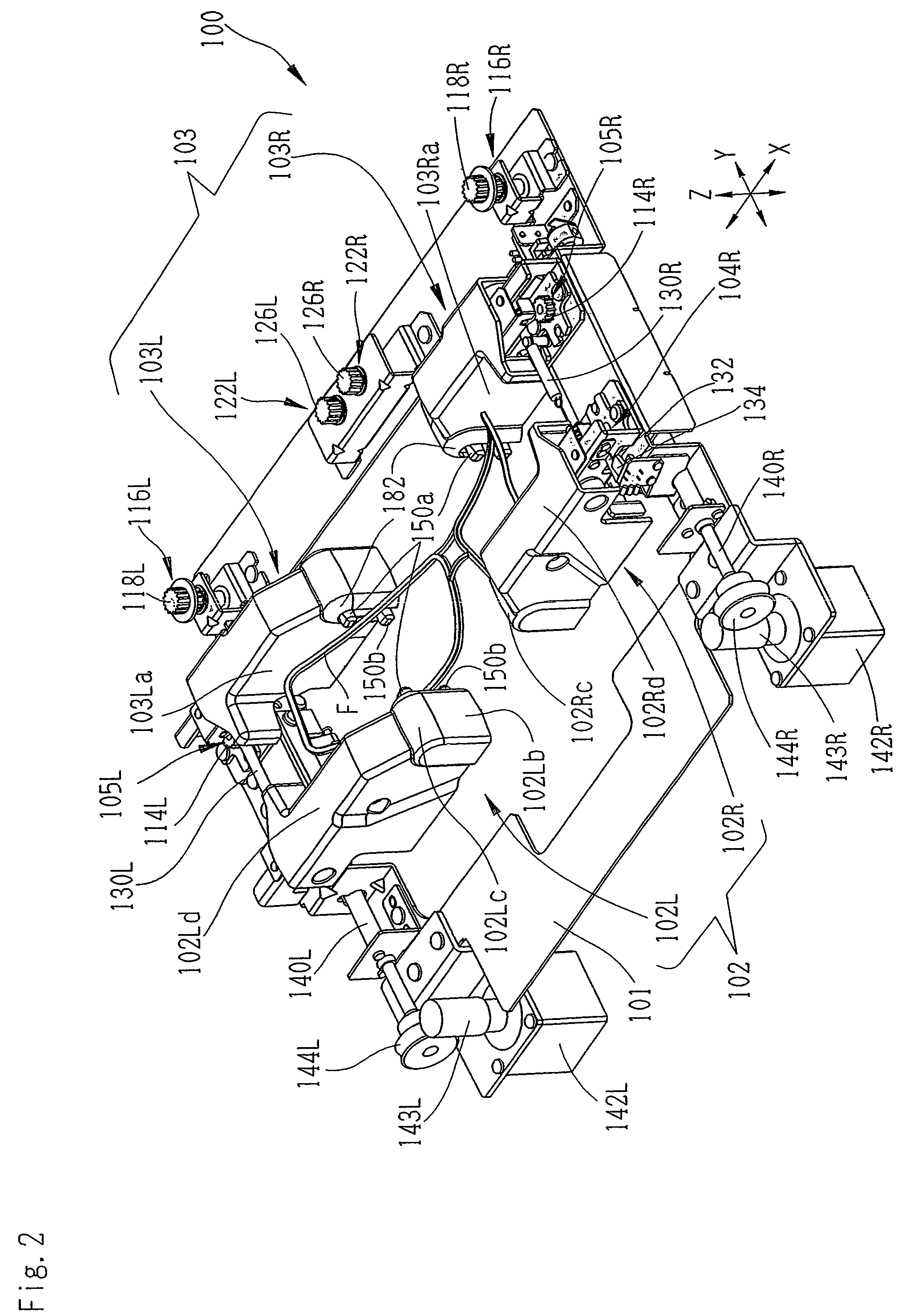
[0031]An embodiment of the invention will now be described with reference to the drawings. FIG. 1A is a schematic exterior view of an eyeglass frame measurement apparatus. An eyeglass frame measurement apparatus 1 includes a frame holding mechanism (holding unit) 100 that holds an eyeglass frame in a desired state, and a measurement mechanism 200 (see FIG. 9) that inserts a tracing stylus into a rim of the eyeglass frame held by the frame holding mechanism 100, and detects movement of the tracing stylus, thereby detecting a three-dimensional shape of the rim (target lens shape). The measurement mechanism 200 is arranged below the frame holding mechanism 100. A mounting portion 300 in which a lens holder 310 (template holder) serving as a holding jig for holding a template and a demo lens is mounted is arranged on the depth side of the apparatus (a rear side of the frame holding mechanism 100).

[0032]A switch section 4 having a measurement start switch and the like is arranged on a fr...


PUM


Abstract

An eyeglass frame measurement apparatus includes: a measurement unit which includes a tracing stylus to be inserted into a groove of a rim of an eyeglass frame, a moving mechanism for moving the tracing stylus along the groove of the rim, and a detector for detecting movement of the tracing stylus, and obtains three-dimensional shape of the rim based on a detected result by the detector; and a holding unit which includes upper and lower sliders for positioning the frame, left and right clamp pins for clamping the rim and left and right contact portion to be contacted with the rim which is clamped by the clamp pins, and holds the frame fixedly. The left and right clamp pins and the contact portions protrude from each of the upper and lower sliders. Each of the contact portions is formed at the periphery of each of the clamp pins.

Description

BACKGROUND OF THE INVENTION[0001](1) Technical Field[0002]The present invention relates to an eyeglass frame measurement apparatus for measuring the shape of a rim of an eyeglass frame.[0003](2) Background Art[0004]A known eyeglass frame measurement apparatus inserts a tracing stylus into a groove of a rim of an eyeglass frame, which is held in a predetermined measurement state by a frame holding mechanism, and detects movement of the tracing stylus, thereby measuring a three-dimensional shape of the rim (target lens shape) (JP-A-2000-314647 (U.S. Pat. No. 6,325,700) and JP-A-2001-174252). As the frame holding mechanism used in the eyeglass frame measurement apparatus, various frame holding mechanisms have been suggested. Such a frame holding mechanism is proposed which has an upper slider and a lower slider that are opened / closed opposite to each other in a vertical direction (refers to a vertical direction in a state where the eyeglass frame is worn), the upper slider and the lowe...

Claims


Application Information

Patent Timeline
Patent Type & Authority Patents(United States)
IPC IPC(8): G01B5/20G01B7/28
CPCG01B5/20G01B5/0004G01B21/20G02C13/00
Inventor MATSUYAMA, YOSHINORI
Owner NIDEK CO LTD
Why Eureka
Try Eureka