Wavelength selective switch

a selective switch and wavelength band technology, applied in the direction of optics, instruments, electrical equipment, etc., can solve the problems of unintentional connection of the network, difficult to reliably block the connection between the input and output ports at non-operational time, and inability to sufficiently respond to combinations of large number of input and output ports, so as to reduce the maximum swinging angle and excellent wavelength band characteristics

Active Publication Date: 2009-12-22
FUJITSU LTD
View PDF2 Cites 9 Cited by
  • Summary
  • Abstract
  • Description
  • Claims
  • Application Information

AI Technical Summary

Benefits of technology

[0014]The present invention has been accomplished in view of the above problems, and has an object to provide a wavelength selective switch capable of blocking the connection between an input side and output side in a non-operating time without degrading the performance at an operating time.
[0017]According to the wavelength selective switch of the present invention, by applying the arrangement in which the center axis of the condenser lens is shifted to the second direction, propagation distances of optical beams between the condenser lens and the movable mirrors are all equal to each other, and therefore, it is possible to realize a disconnection state between the input and output ports at the non-operating time without a substantial loss difference between the lights of respective wavelengths which are led from the input port to the output port at the operating time, while ensuring excellent characteristics of respective wavelength bands. Further, since the configuration is such that the angles of the reflecting surfaces of the movable mirrors are offset to the second direction which is different from the first direction in which the input and output ports are arranged, it is also possible to reduce a maximum swinging angle of each movable mirror for when the switching of the connection between the input and output ports is made, compared with the case where the movable mirrors are offset to the first direction as in the conventional technology.

Problems solved by technology

Therefore, in the optical switch which is in a non-operating state due to any apparatus failure, if the path between an input side and an output side is connected, there is caused a problem in that the network is unintentionally connected.
However, in the case where a large number of input and output ports is disposed to the conventional wavelength selective switch as described above, by merely offsetting the angle of each movable mirror to the Y-direction as shown in FIG. 14 and FIG. 15, it becomes hard to reliably block the connection between the input and output ports at the non-operating time.
Therefore, there is caused a problem in that it becomes impossible to sufficiently respond to combinations of large number of input and output ports by merely offsetting the angle of each movable mirror to only the Y-direction.
Therefore, there are caused problems in that a loss difference occurs between the lights of respective wavelengths, which are reflected by the respective movable mirrors to be led to the output port, and also, a beam of the light condensed on the reflecting surface of each movable mirror is spread so that a wavelength band of the light becomes narrower.

Method used


Image

  • Wavelength selective switch
  • Wavelength selective switch
  • Wavelength selective switch

Examples


first embodiment

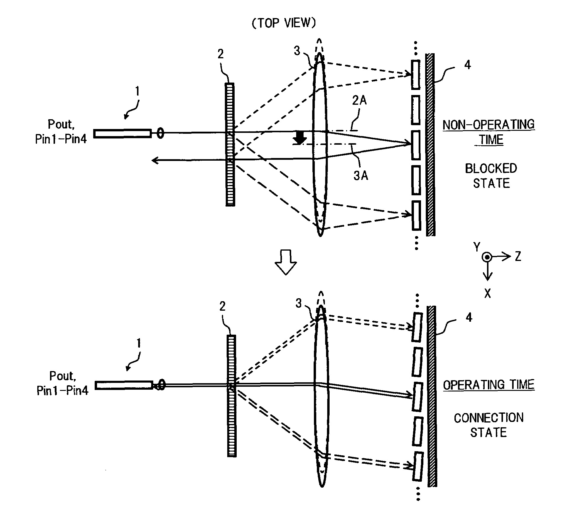
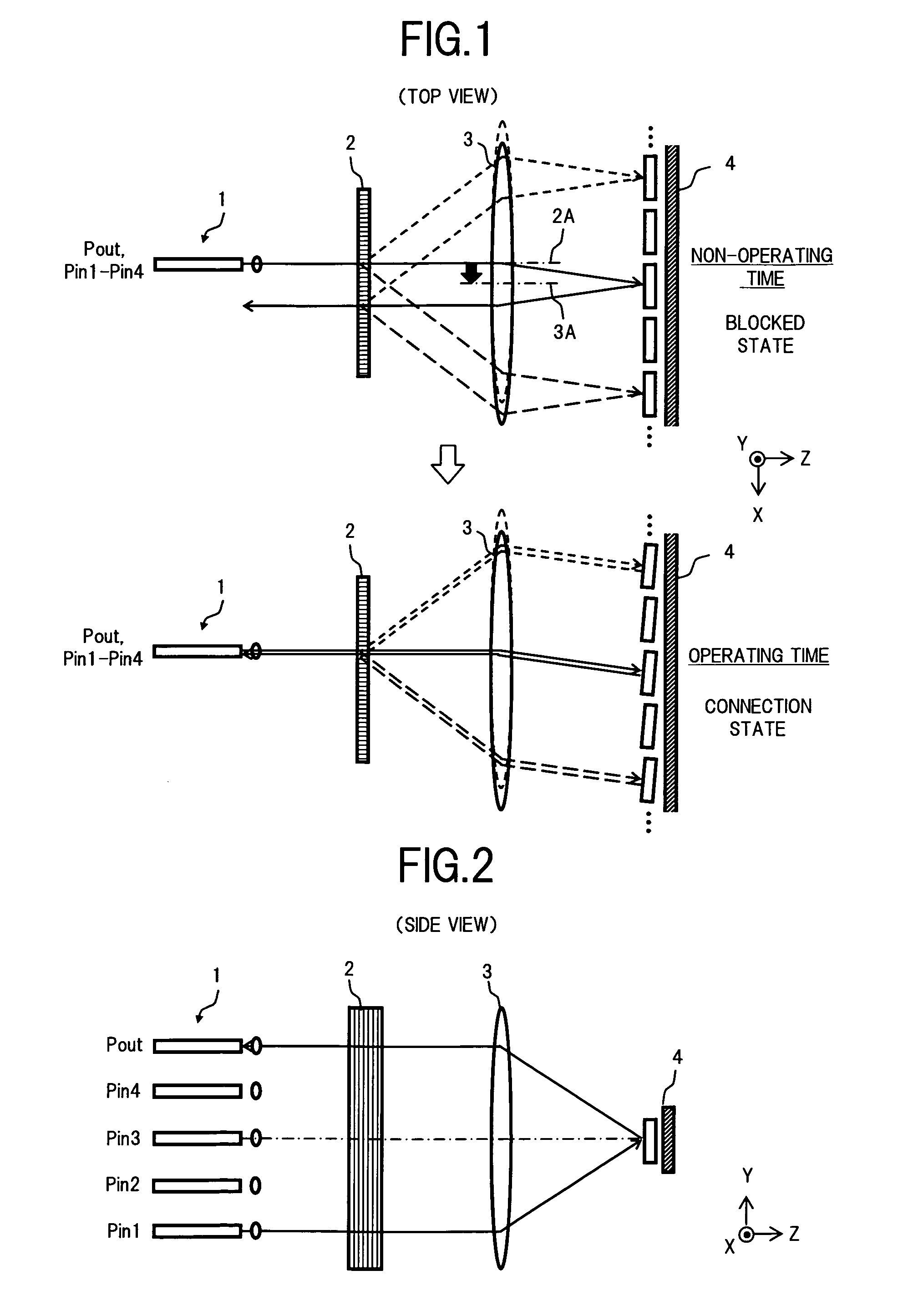
[0037]FIG. 1 and FIG. 2 are diagrams showing a configuration of an essential part of a wavelength selective switch according to the present invention, and FIG. 1 is a top view and FIG. 2 is a side view. Incidentally, the configuration of the entirety of the present wavelength selective switch is basically same as a configuration of a conventional wavelength selective switch shown in FIG. 13.

[0038]In FIG. 1 and FIG. 2, the wavelength selective switch in the first embodiment comprises, for example: an input and output optical system 1 in which input ports Pin1 to Pin4 and an output port Pout are arranged in a first direction (Y-direction); a diffraction grating 2 serving as a spectral element, which separates lights emitted from the input ports Pin1 to Pin4 of the input and output optical system 1 according to wavelengths, to angularly disperse the separated lights to a second direction (X-direction); a condenser lens 3 which condenses the lights of respective wavelength angularly dis...

second embodiment

[0051]Next, there will be described the present invention.

[0052]FIG. 6 is a diagram showing a configuration of an essential part of a wavelength selective switch according to the second embodiment of the present invention.

[0053]In FIG. 6, the present wavelength selective switch is an application example of the configuration in the first embodiment shown in FIG. 1 and FIG. 2, in which the center axis 3A of the condenser lens 3 is shifted not only to the X-direction but also to the Y-direction. To be specific, as shown in a black arrow line on an upper stage of FIG. 6, similarly to the first embodiment, the center axis 3A of the condenser lens 3 is shifted to the X-direction relative to the axis 2A passing through the center of spreading angle to the X-direction of the optical beams output from the diffraction grating 2. At the same time, as shown by a black arrow line on a lower stage of FIG. 6, the center axis 3A of the condenser lens 3 is shifted to the Y-direction relative to an o...


PUM

PropertyMeasurementUnit
wavelengthsaaaaaaaaaa
spreading angleaaaaaaaaaa
focal distanceaaaaaaaaaa

Abstract

A wavelength selective switch of the present invention angularly disperses lights output from a plurality of input ports of an input and output optical system, to an X-direction, according to wavelength, by a diffraction grating to supply the dispersed lights to a condenser lens. The condenser lens is arranged so that a center axis thereof is shifted to the X-direction relative to an axis passing through the center of spreading angle to the X-direction of output beams from the diffraction grating, and accordingly, at a non-operating time, the light of each wavelength passed through the condenser lens is incident on each movable mirror being tilted by an offset angle corresponding to a shift amount of the condenser lens. As a result, it becomes possible to block the connection between an input side and an output side at the non-operating time without degrading the performance at an operating time.

Description

BACKGROUND OF THE INVENTION[0001]1. Field of the Invention[0002]The present invention relates to a wavelength selective switch which separates a wavelength division multiplexed light for each wavelength by a spectral element, and thereafter, condenses the separated lights using a lens to reflect the condensed lights by movable mirrors, to thereby switch paths for the lights of respective wavelengths, and in particular, to a wavelength selective switch by which the connection between an input side and an output side is blocked at a non-operating time.[0003]2. Description of the Related Art[0004]In a photonic network of which connection between nodes is a ring type or a mesh type, there has been adopted a structure in which, in the case where a failure occurs in a certain node or a certain path, in order to avoid the degradation of communication service over the entire network, an optical signal is transmitted via a node or a path in which a failure does not occur, to improve the comm...

Claims


Application Information

Patent Timeline
Patent Type & Authority Patents(United States)
IPC IPC(8): G02B6/26G02B26/08G02B6/42H04J14/00G02F1/29G02B26/10G02B26/12
CPCG02B6/356G02B26/0833G02B6/3512G02B6/29313G02B6/29311G02B6/3558G02B6/32
Inventor YAMAMOTO, TSUYOSHIAKASHI, TAMOTSUSHIBATA, KOHEIAOTA, HIROFUMIYAMASHITA, SHINJI
Owner FUJITSU LTD
Why Eureka
Try Eureka