Optical amplifier with optimal gain excursion for different input powers

an optical amplifier and input power technology, applied in the field of amplifiers, can solve the problems of unacceptable gain unbalance over the band of the multiplex, complex implementation, and high cost, and achieve the effect of maximizing signal-to-noise ratio, minimizing losses, and easy adjusting of the gain of an optical amplifier

Inactive Publication Date: 2001-06-12
ALCATEL LUCENT SAS
View PDF7 Cites 2 Cited by
  • Summary
  • Abstract
  • Description
  • Claims
  • Application Information

AI Technical Summary

Benefits of technology

is thus to provide a solution enabling the gain of an optical amplifier to be adapted easily, e.g. as function of line losses over the section of optical fiber that precedes the amplifier in a transmission system, so as to ensure flat gain for the amplifier. Another object of the invention is to minimize losses and maximize signal-to-noise ratio as a result of such matching.

Problems solved by technology

One of the problems encountered when installing optical fiber transmission systems is that the line losses over the link sections between the various amplifiers present values that are different; under such circumstances, the amplifiers receive different powers, such that system performance can be improved if each amplifier is matched to the line loss of the section of fiber that precedes it, thereby ensuring gain that is flat in spite of variations in applied input power.
That solution is complex to implement and it is expensive.
In that article, the problem encountered is that of variations in gain or "gain unbalance" in each of the amplifiers over the band of the multiplex.
That defect can be accepted in each amplifier, but after several stages of gain, such gain unbalance becomes unaccepted over the band of the multiplex.
Firstly, the proposed circuit has only one filter for three amplification stages: after all the object is to correct equalization as rarely as possible, and only when that turns out be necessary, i.e. when accumulated gain unbalance is large; the article specifies that prior techniques are unsuitable for "adjustable compensation of accumulated gain unbalance".
Finally, the solution proposed does not enable the amplifier to be matched to the power it receives, but serves at best to equalize accumulated gain in a single direction.
This comes from the tuning range of the Mach Zender filter used; the filter cannot be tuned over a wavelength band that is sufficient to change the sign of the slope of the filter; in addition, even if that were possible, changing the sign of the slope of the filter would increase gain unbalance over the wavelength band of the multiplex.

Method used


Image

  • Optical amplifier with optimal gain excursion for different input powers
  • Optical amplifier with optimal gain excursion for different input powers
  • Optical amplifier with optimal gain excursion for different input powers

Examples


Embodiment Construction

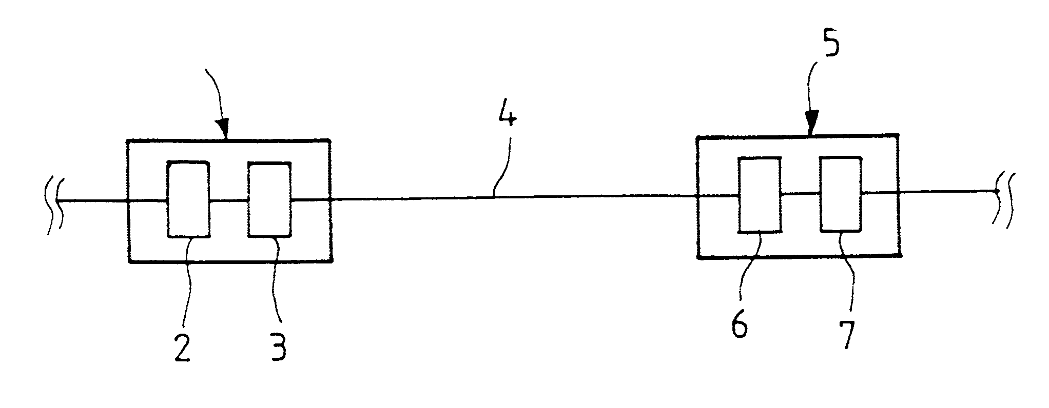
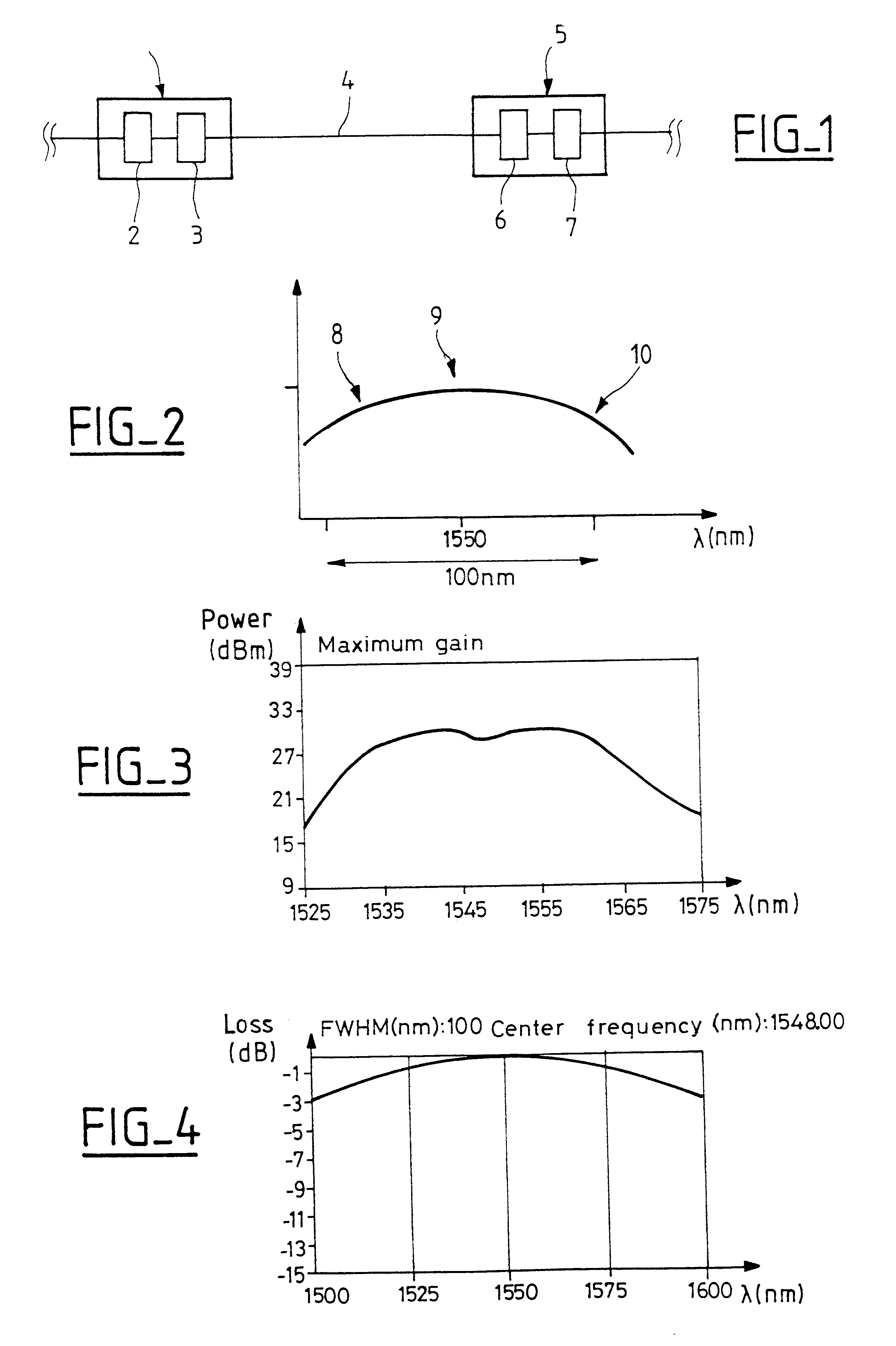
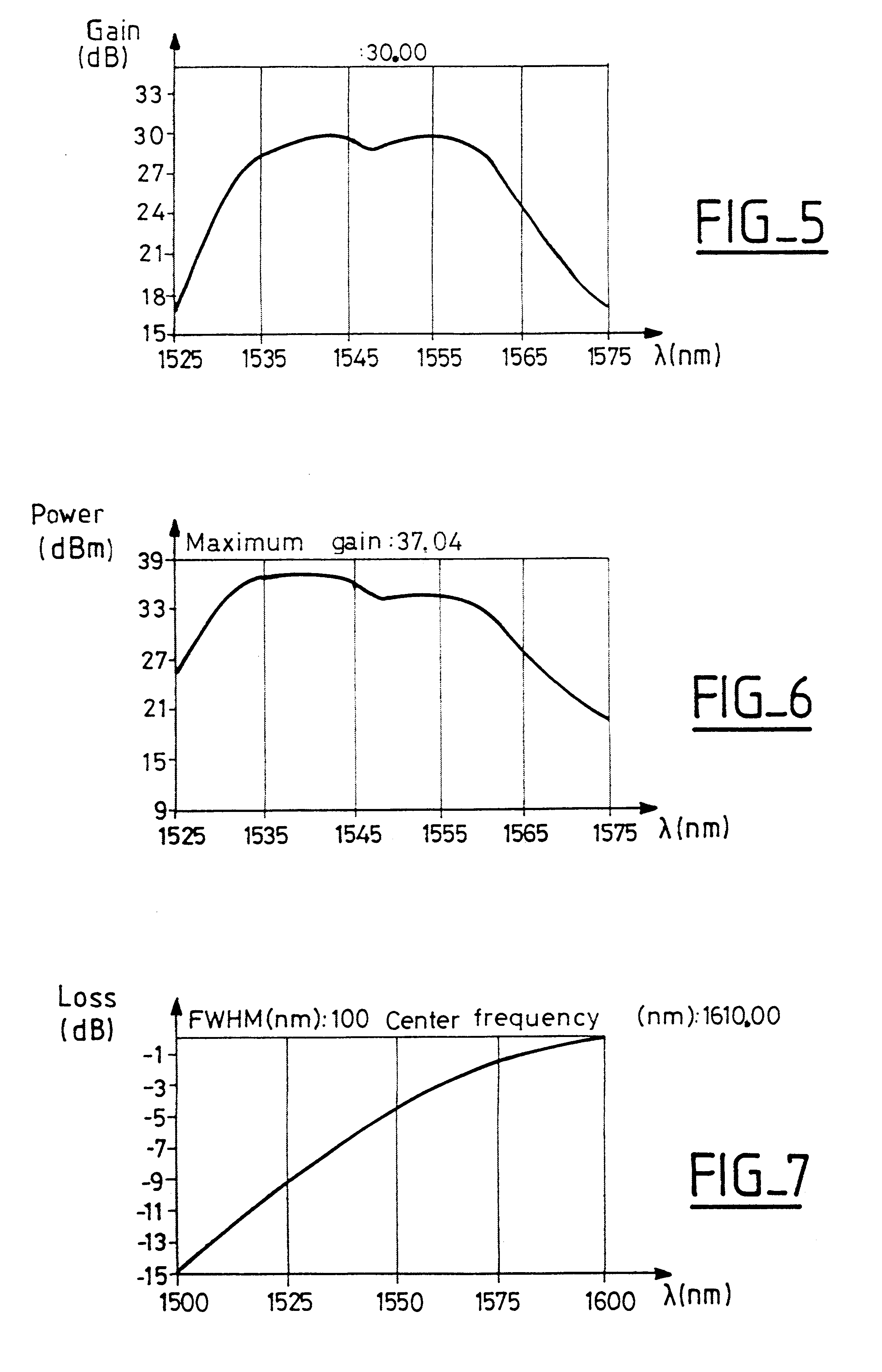
In order to enable an amplifier to be matched to line loss in the preceding section of a link, instead of changing the gain of the amplifier, the invention proposes selecting an amplifier having gain excursion that is optimal for the mean inlet power and associating the amplifier with a filter enabling gain variations to be corrected for different input powers. In other words, the amplifier presents gain that is as flat or as equalized as possible for the mean input power. The filter is a filter whose transfer function is bell-shaped, with its center wavelength being tunable over a range that is large enough to be able to correct for variations in gain. In other words, the filter is tunable over a range that is large enough to ensure that in the wavelength band of the link, the slope of the filter transfer function can change sign. This makes it possible to compensate for variation caused in gain by changes in input power applied to the amplifier.

FIG. 1 is a diagram of a transmissio...


PUM


Abstract

The invention relates to optical fiber apparatus comprising an amplifier having optimal gain excursion over a given wavelength band for given input power, and a filter having a bell-shaped transfer function, with the center wavelength of the filter being tunable over a range that is sufficient to enable the gain excursion of the amplifier over said wavelength band to be reduced when the power received by the amplifier is different from said given input power. The invention makes it possible to match amplifier apparatuses to line losses while minimizing overall loss.

Description

The present invention relates to an optical amplifier apparatus presenting optimal gain excursion for different input powers; the invention also relates to a transmission system including such an apparatus, and to a method of matching an optical amplifier to an input power.The invention relates to optical amplifiers, and more particularly to optical amplifiers designed to be used in optical fiber transmission systems with wavelength division multiplexing (WDM). Such amplifiers are used at regular intervals to compensate line losses. The amplifiers over an entire link are preferably identical, presenting gain that is as flat as possible over the entire wavelength band used in the transmission system, for given input power. One of the problems encountered when installing optical fiber transmission systems is that the line losses over the link sections between the various amplifiers present values that are different; under such circumstances, the amplifiers receive different powers, su...

Claims


Application Information

Patent Timeline
Patent Type & Authority Patents(United States)
IPC IPC(8): H04B10/17H01S3/06H01S3/10H04B10/02H04B10/18H04B10/29
CPCH04B10/2912H04B10/2935
Inventor BAYART, DOMINIQUEDESTHIEUX, BERTRAND
Owner ALCATEL LUCENT SAS
Why Eureka
Try Eureka