Wireless telecommunication system, transmitter and receiver

a wireless telecommunication system and transmitter technology, applied in the field of multi-input multiple output multi-output transmission technology, can solve problems such as and achieve the effect of preventing the decrease of transmission speed and shortening the time required

Inactive Publication Date: 2009-12-22
FUJITSU LTD
View PDF16 Cites 26 Cited by
  • Summary
  • Abstract
  • Description
  • Claims
  • Application Information

AI Technical Summary

Benefits of technology

[0030]The purpose of the present invention is to shorten the time required for a handover, thereby preventing a decreased transmission speed at the time of carrying out a handover.
[0032]Each receiving unit measures a reception quality and received power transmitted from a transmission unit for each stream. A handover is carried out in the unit of a stream if the result of a measurement indicates that it is preferable that a handover is carried out. A discard, transfer or retransmission process for data at the current base station is no longer required, hence shortening the time required for a data transmission.
[0037]According to the present invention, once a handover is carried out for each of the data stream, there is no need for a current transmission apparatus to discard, retransmit or transfer data, and therefore it is possible to shorten the time required for the handover processing. Shortening the time required for the handover processing prevents a reduced transmission speed at the time of carrying out a handover.

Problems solved by technology

There is a problem of a handover process being time consuming as much as the processing of retransmitting or transferring the data taking time, hence resulting in a decreased transmission speed.

Method used


Image

  • Wireless telecommunication system, transmitter and receiver
  • Wireless telecommunication system, transmitter and receiver
  • Wireless telecommunication system, transmitter and receiver

Examples


first embodiment

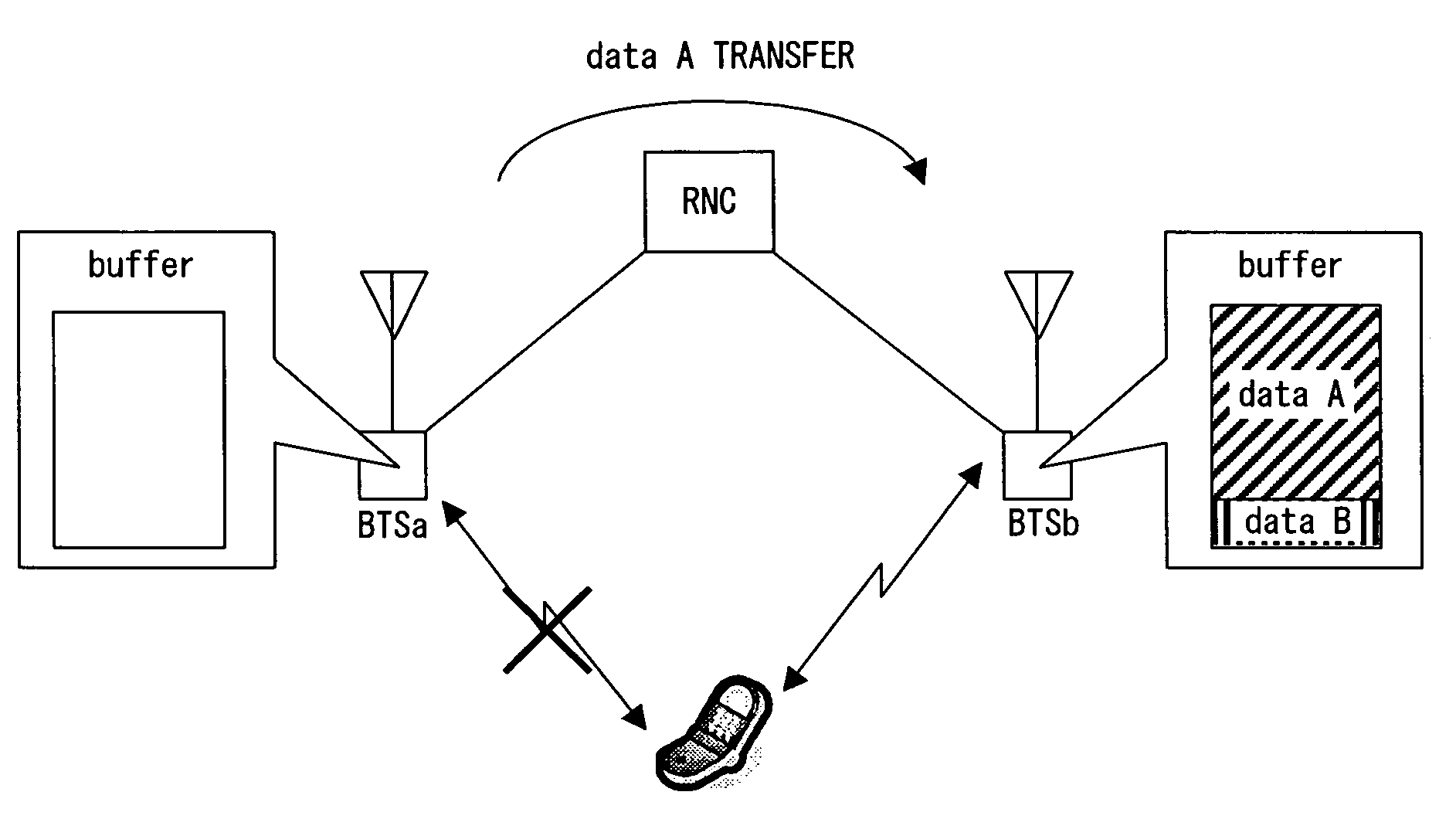
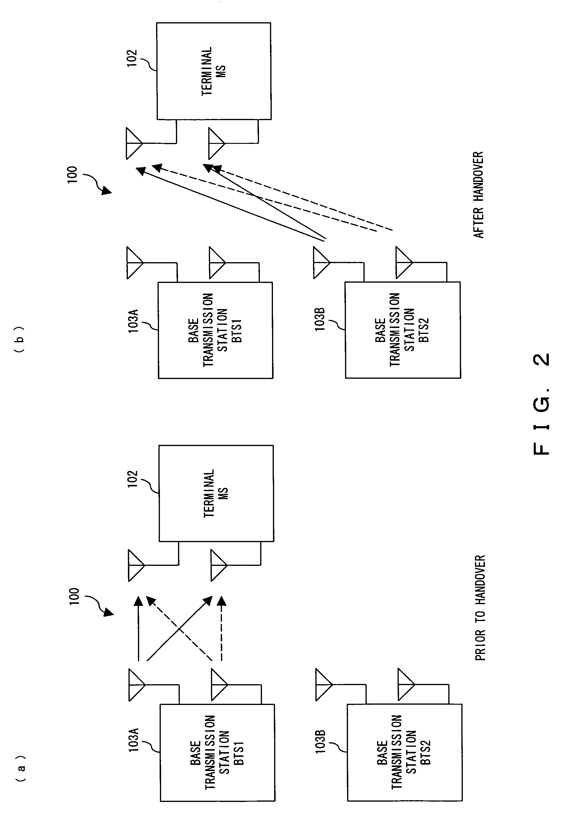
[0075]FIG. 12 is a conceptual diagram of a handover method according to the present invention. A wireless telecommunication system 1 using a MIMO transmission technique which adopts HSDPA (high speed downlink packet access) as one standard specification of W-CDMA comprises base transmission stations BTS 3 (BTS3a and BTS3b) and a mobile station (MS) 2. As shown by FIG. 12(a), the mobile station 2 receives a plurality of data streams via the base transmission station BTS3a prior to a handover. With regard to a received power for the same data stream, if a received power from another base transmission station, which the own mobile station 2 is not connected to, is larger than that from the connected base transmission station, a handover is carried out for the aforementioned data stream. As shown by FIG. 12(b), a data stream after the handover being carried out is transmitted to the mobile station 2 via a base transmission station BTS3b. The data streams for which a handover is not carr...

second embodiment

[0128]FIG. 24 shows a comprisal of the mobile station 2 carrying out a handover according to the second embodiment. The description is of a different point as compared to the comprisal of the mobile station 2 according to the first embodiment shown by FIG. 13. Note that the base transmission station 3 for carrying out a handover according to the present embodiment is the same as that of the base transmission station according to the first embodiment as shown by FIG. 15, and therefore a description thereof is omitted here.

[0129]The mobile station 2 according to the second embodiment shown by FIG. 24 differs from the mobile station 2 according to the first embodiment where the former comprises received power measurement units 27 (27A, 27B and 27C) for measuring a received power of a received pilot signal received by way of each antenna Rx. The received power measurement units 27A, 27B and 27C measure the received powers of signals received by way of respective antennas and provide the...

third embodiment

[0135]A handover method according to this embodiment is the same as in the case of the second embodiment where the path for a data stream to carry out a handover is switched to a common target base transmission station, while the difference from the second embodiment is that a target station is determined based on statistical data of the optimal target base transmission station for each data stream. Since the comprisals of the mobile station 2 and base transmission station 3 according to the present embodiment are the same as in the case of the first embodiment, descriptions of them are omitted in the following description of a handover method according to the present embodiment.

[0136]FIG. 26 is a flow chart of a handover processing according to the third embodiment. The processing shown by FIG. 26 is executed at the time of receiving a pilot signal from the base transmission station 3 as in the case of the processes shown by FIGS. 17 and 25. Note that the flow chart shown by FIG. 2...


PUM


Abstract

In a wireless telecommunication system for transmitting a plurality of streams from a base transmission station comprising a plurality of antennas to a mobile station comprising a plurality of antennas, the base transmission station respectively transmits, by way of a plurality of the antennas, each stream obtained by dividing data to be transmitted. The mobile station respectively receives each stream by utilizing the plurality of antennas. A measurement unit respectively measures a reception quality or received power from each antenna relating to a stream. A change over unit carries out a handover for each stream according to a measurement result by the measurement unit.

Description

BACKGROUND OF THE INVENTION[0001]1. Field of the Invention[0002]The present invention relates to an MIMO (multiple input multiple output) transmission technology for transmitting a plurality of streams by way of a plurality of antennas.[0003]2. Description of the Related Art[0004]In a wireless telecommunication system, mobile terminals (i.e., terminals) are enabled to continue a telecommunication if a received power, et cetera, is reduced by selectively changing a connected base station over to an optimal one based on a received power, a reception quality, et cetera, from surrounding base stations (e.g., refer to patent documents 1, 2, 3 and 4; and a non-patent document 1). An example of a wireless telecommunication system is the recently propagated W-CDMA (Wideband Code Division Multiple Access) system.[0005]FIG. 1 exemplifies a configuration of a telecommunication system adopting the W-CDMA system. The terminal (i.e., a mobile station, MS) receives signals from a plurality of base...

Claims


Application Information

Patent Timeline
Patent Type & Authority Patents(United States)
IPC IPC(8): H04B7/00H04W36/02H04W36/30
CPCH04B7/04H04W36/30H04W36/28H04W36/02H04B7/0689H04B7/0413
Inventor ODE, TAKAYOSHIKAWABATA, KAZUO
Owner FUJITSU LTD
Why Eureka
Try Eureka