Loading and unloading apparatus

a technology for unloading and equipment, applied in the field of unloading equipment, can solve the problems of limited manual labor, all manual interference with the actual placing, etc., and achieve the effect of a better and less demanding work environmen

Inactive Publication Date: 2010-01-05
VESTERGAARD MARTIN
View PDF10 Cites 37 Cited by
  • Summary
  • Abstract
  • Description
  • Claims
  • Application Information

AI Technical Summary

Benefits of technology

[0009]It is, therefore, an object of the present invention to provide a loading and unloading apparatus which overcomes these problems as well as providing a complete system which may advantageously be used in order to provide a better and less demanding work environment for the personnel involved.

Problems solved by technology

Ensuring the unloading, the conveying device will transport the item such that all manual interference with the actual placing of the item is limited to manipulate the loading and unloading apparatus into a position where it is desirable to either unload a piece of luggage or to load a piece of luggage unto the conveyor device.
In this manner, the manual labour required in order to place an item correctly or remove an item is limited to the actual placing of the item in the stack i.e. next to other items, or removing the item by sliding it onto the tip of the conveyor device.

Method used


Image

  • Loading and unloading apparatus
  • Loading and unloading apparatus
  • Loading and unloading apparatus

Examples


Embodiment Construction

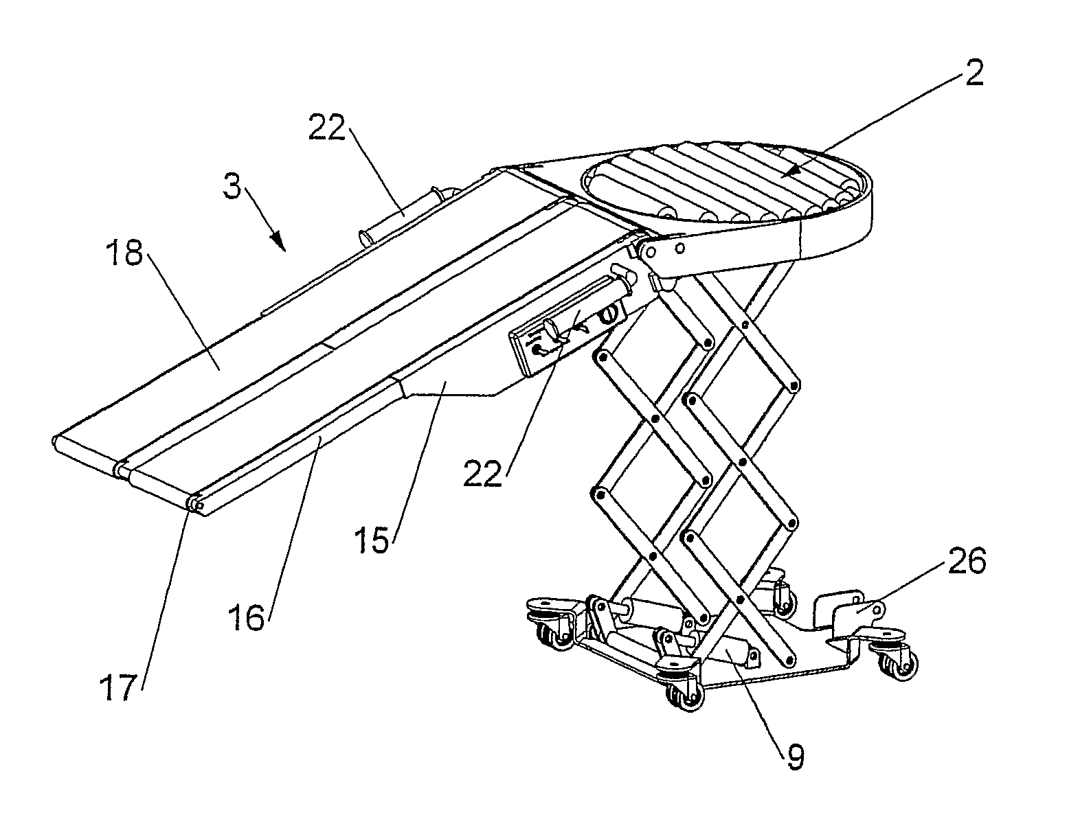
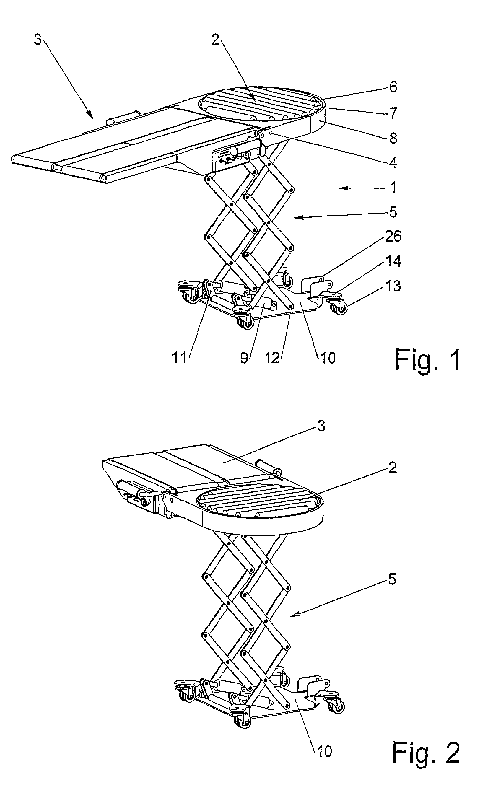
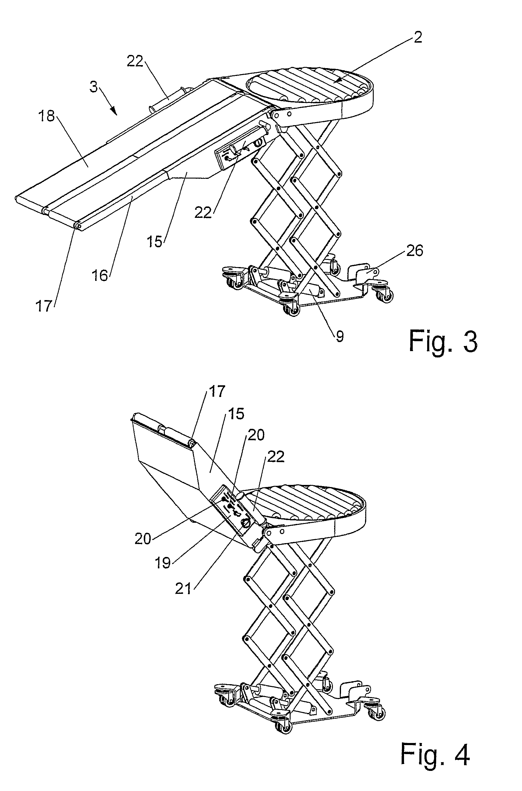
[0041]In FIG. 1, an apparatus 1 according to the invention is illustrated. The apparatus comprises a roller table 2 arranged adjacent to a conveyor device 3. The conveyor device 3 is pivotably mounted to the roller table 2 in this embodiment by a hinge like construction 4. It should, however, be noted that any other suitable manner of hingely connecting these two elements such that the conveyor device 3 may tilt or pivot in relation to the roller table 2 may be utilised within the scope of the invention.

[0042]The roller table 2 and the associated conveyor device 3 are pivotably mounted on the carrying structure 5.

[0043]The pivotal arrangement may be in the shape of a first frame 7 wherein the rollers 6 of the roller table 2 are arranged. The first frame 7 is arranged inside a second frame 8 such that the first and second frames 7,8 may relatively be displaced in a plane parallel to the transport plane of the roller table 2. In this manner, it is possible to direct the conveyor devic...


PUM


Abstract

The present invention provides a loading and unloading apparatus comprising in mutual cooperation a conveyor device (3) adjacent a roller table (2), where said conveyor device and roller table are pivotably mounted on a carrying structure (5), which structure, in use is vertically extendable and retractable.

Description

[0001]This application claims the benefit of PCT / DK2004 / 000214 filed Mar. 26, 2004, which is hereby incorporated by reference in its entirety.BACKGROUND OF THE INVENTION[0002]The present invention relates to a loading and unloading apparatus as well as a loading and unloading system comprising an apparatus as will be described below.[0003]Although the inventive apparatus and loading and unloading system described in the present application may be utilised in a number of situations, the invention is especially advantageous for use in places where it is difficult to gain access or use other means for handling goods such as for example loading bays in aircrafts, boats, trains or other vehicles. That is to say that the invention is particularly advantageous for use in theses situations, but the inventive concept should not be limited as the invention may be used advantageously in other connections as well.[0004]Within this application, loading and unloading of aircraft bays will be used...

Claims


Application Information

Patent Timeline
Patent Type & Authority Patents(United States)
IPC IPC(8): B65G21/10B64F1/32B64D9/00B65G13/12B65G21/14B65G41/00B65G67/02
CPCB64D9/00B64F1/32B65G13/12B65G21/14B65G41/005B65G41/008B65G67/08
Inventor VESTERGAARD, MARTIN
Owner VESTERGAARD MARTIN
Why Eureka
Try Eureka