Lower limb function training device

a technology for lower limbs and training devices, applied in chiropractic devices, gymnastics exercises, physical therapy, etc., can solve the problems of many times suited exercise not achieving the expected improvement, difficult to perform passive exercise at one's convenience, and many disabled people, so as to prevent excessive exercise of patients

Inactive Publication Date: 2010-01-05
TAKIZAWA SHIGEO +1
View PDF10 Cites 12 Cited by
  • Summary
  • Abstract
  • Description
  • Claims
  • Application Information

AI Technical Summary

Benefits of technology

[0060]Therefore, it can be prevented that patients exercise more than a set value of the number of times of a reciprocating motion. Consequently, preventing the excessive exercise of a patient.
[0080]In such a case, Data for research and management of the momentum of a patient can come to hand easily.

Problems solved by technology

However, it is difficult to perform passive exercises at one's convenience due to human problems.
Also in the cases that a director or caregiver are not close by, the disabled person who does not keep the caregivers instruction of the exercise repetitions and exceeds the equivalent range of the suited exercise by many times will not achieve the expected improvement.
Although, muscular-strength reinforcement became the purpose of training to the disabled person with whom the improvement progressed, a load is not applied at the time of exercises and it was not able to be used for muscular-strength reinforcement.

Method used


Image

  • Lower limb function training device
  • Lower limb function training device
  • Lower limb function training device

Examples


first embodiment

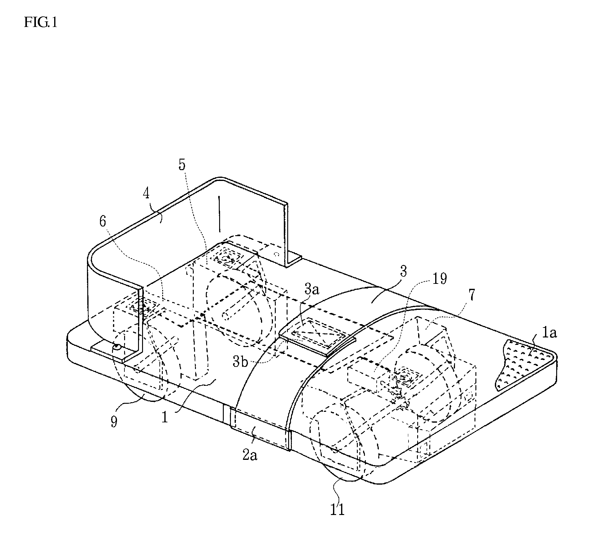
[0108]I explain a lower limb function training device in this invention by using FIG. 1 and FIG. 8.

[0109]FIG. 1 is a perspective view of a lower limb function training device of the first embodiment.

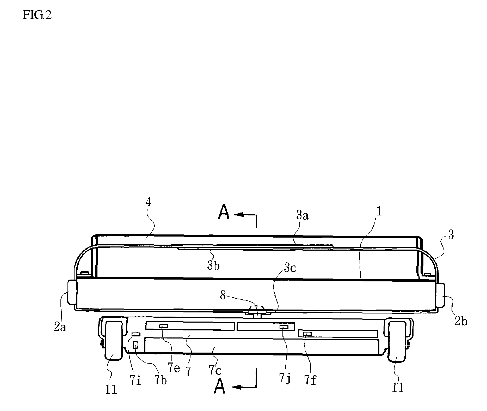
[0110]FIG. 2 is a front view of FIG. 1.

[0111]FIG. 3 is a rear view of FIG. 1.

[0112]FIG. 4 is a A-A cross section view of FIG. 2.

[0113]FIG. 5 is a side view while using, which sets and fixes the two legs.

[0114]FIG. 6 is a side view showing the state of performing Plantar Flexion exercise.

[0115]FIG. 7 is a control circuit diagram.

[0116]FIG. 8 is a flowchart in case, which the connection between a wheel and a motor are cut.

[0117]Furthermore, the drawing of a rear wheel support of a right and left part is omitted in FIG. 2.

[0118]Also, the drawing of the front wheel support parts is omitted in FIG. 3.

[0119]A foot rest (1) is formed with wood in midair with a plane abbreviation rectangular (when necessary another material can be used in place of wood, such as plastic).

[0120]The foot rest (1) i...

second embodiment

[0184]Next, I explain the second embodiment by using FIG. 9 to FIG. 13.

[0185]FIG. 9 is a perspective view of a foot rest of the second embodiment.

[0186]FIG. 10 is a perspective view of a foot rest move stand of the second embodiment.

[0187]FIG. 11 is a perspective view of the second embodiment.

[0188]FIG. 12 is a side view of the second embodiment.

[0189]FIG. 13 is a perspective view of the second embodiment in a usage state.

[0190]Furthermore, I omit the detailed explanation of composition elements parity to the first embodiment by putting the same mark in the explanation of the second embodiment.

[0191]The second embodiment consists of a foot rest (1) and a foot rest cart (22) as a measuring instrument, and the similar functions to the first embodiment are realized by combining a foot rest (1) and a foot rest cart (22).

[0192]Same as the first embodiment, both a heel support part (4) and setting band (3) assemble a foot rest (1) of this embodiment.

[0193]Several wheels (21) that may move...

third embodiment

[0231]Next, I explain the third embodiment by using FIG. 14 and FIG. 17.

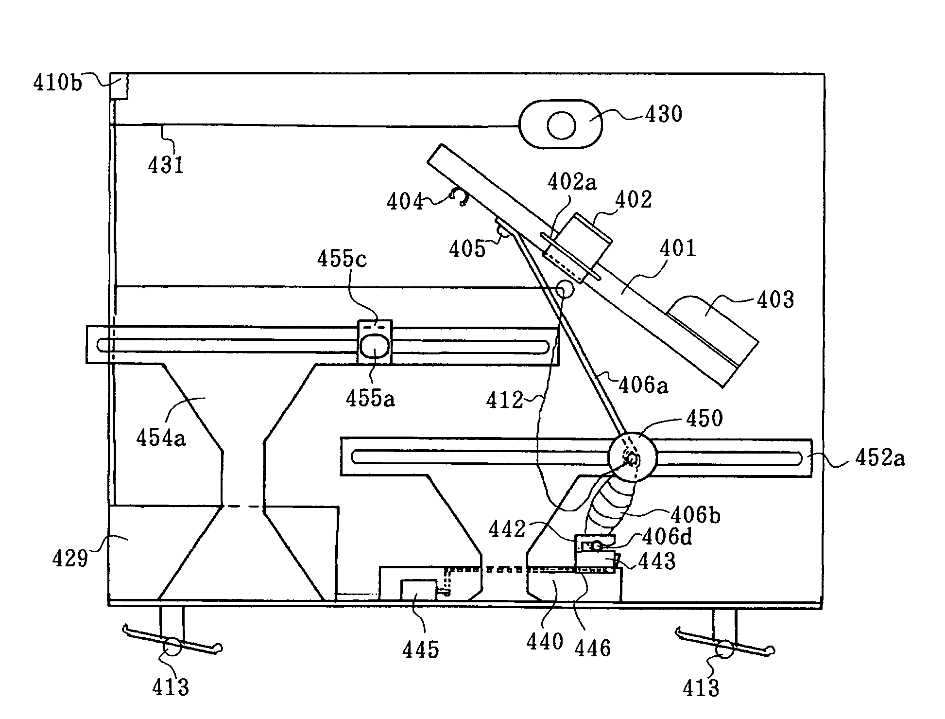
[0232]FIG. 14 is a side view of a lower limb function training device of the third embodiment.

[0233]FIG. 15 is a perspective view of FIG. 14.

[0234]FIG. 16 is a side view while in use, which sets and fixes the two legs.

[0235]FIG. 17 is a side view of the modification of the third embodiment,

[0236](a) is a view of the first modification,

[0237](b) is a view of the 2nd modification.

[0238]A foot rest (301) is formed of plastic (or can necessarily be made of wood, etc.) and a space inside with a plane similar to a rectangle.

[0239]The foot rest (301) has an area of sufficient width that can set both feet shown as FIG. 16 (for example, the size of the side about 20 cm and about 25 cm, length).

[0240]Therefore, a disabled person can set both a foot with a disability, which has hemiparesis of lower extremities of a nerve, decline of the lower extremities muscular strength that originates from a plasmotomy of Achilles' tend...


PUM


Abstract

A lower limb function training device which the patient themselves can use safely with no sense of fear, which is used to prevent or improve a drop foot contracture or to expand the excursion of a joint while preventing the patient from using it over an appropriate amount of exercise to the utmost, which allows the patient to select the type of exercise, and which enables measurement of state of the body. The device is provided with a foot rest support structure, a foot rest drive mechanism and a round-trip movement sensing device, and a brake device for braking the round-trip movement of the foot rest when the count reaches a preset value. The device is provided with a foot rest support structure, a foot rest drive mechanism and at least one contact sensor on a surface of the foot rest, and a brake device for braking the back-and-forth movement of the foot rest when the at least one contact sensor detects the soles of the feet contacting.

Description

[0001]This application is a continuation of application Ser. No. 10 / 779,126, filed Feb. 12, 2004, now U.S. Pat. No. 7,322,904, which is a divisional of application Ser. No. 09 / 581,463 filed on Jun. 11, 2001, now U.S. Pat. No. 6,780,142.TECHNICAL FIELD[0002]This invention is related to a lower limb function training device which makes the patient feel safe to use and is intended to prevent and / or improve the contracture of equines and also to expand the joints' range of motion.BACKGROUND TECHNOLOGY[0003]In the case of disorders where someone has a disability as a result of hemiparesis after apoplexy, a decline of muscular strength of the lower extremities is caused by the rupture of the Achilles' tendon and / or disabilities of the range of motion in the joint of a leg or knee originating in a bone fracture of the lower extremities and other conditions if left untreated, an ankle or knee becomes a contracture and chronic disabilities of the lower extremities have been originated.[0004]...

Claims


Application Information

Patent Timeline
Patent Type & Authority Patents(United States)
IPC IPC(8): A63B71/00A63B22/00
CPCA61H1/024A63B21/4015A63B21/00178A63B21/00181A63B23/0494A63B23/085A63B24/0003A61H1/0266A63B21/0058A63B21/012A63B21/023A63B21/0552A63B22/20A63B2208/0233A63B2220/17A63B2220/30A63B2220/40A63B2220/801A63B2220/806A63B2220/807A63B22/203A61H2201/0157A61H2201/1215A61H2201/164A61H2201/1642A61H2201/1664A61H2201/1666A61H2201/1676A61H2201/5058A61H2201/5079A61H2201/5084A61H2203/0431
Inventor TAKIZAWA, SHIGEOTAKIZAWA, KYOKO
Owner TAKIZAWA SHIGEO
Why Eureka
Try Eureka