
Servo controller

a servo controller and controller technology, applied in the direction of electric programme control, program control, instruments, etc., can solve the problems of increasing synchronization error, synchronization characteristic inferior to that of feed axis, and increasing synchronization error, so as to reduce manufacturing cost, reduce load, and simple structure

Inactive Publication Date: 2010-02-02
FANUC LTD
View PDF26 Cites 26 Cited by
  • Summary
  • Abstract
  • Description
  • Claims
  • Application Information

AI Technical Summary

Benefits of technology

This approach enhances machining accuracy and efficiency by minimizing synchronization errors, even under conditions of high inertia or high-speed operations, and allows for flexible adaptation to different machining specifications.

Problems solved by technology

However, in the case where inertia of the rotary axis is increased according to an enhancement of the rigidity of the rotary axis or in the case where the rotary axis is rotated at a high speed, the servo characteristic of the rotary axis is inferior to that of the feed axis.
Further, the synchronization error is increased by a cutting disturbance such as a change in the depth of cut of a cutting tool or a shock caused at the time of starting cutting.
Furthermore, the synchronization error is increased by the friction.
Being affected by the cutting disturbance and friction, the accuracy of machining a screw is deteriorated.
For the above reason, there is a high possibility that the learning control cannot exhibit the effect because it is restricted by the maximum torque of a motor.
In this way, even when the axes are driven by the same synchronization command, the speed of the rotary axis must be higher than that of the feed axis by 10 times. Therefore, even when both axes are rotated by the same acceleration and deceleration time constant, a higher torque must be given to the rotary axis, which is very difficult from the practical viewpoint.

Method used


Image

  • Servo controller
  • Servo controller
  • Servo controller

Examples


second embodiment

[0062]In this connection, it should be noted that the present invention is not limited to the above specific embodiment. Various variation may be made. For example, as a variation of the second embodiment, as shown in FIG. 8, the synchronization error calculation means 15 is provided in the numerical controller 30, and the correction data can be transferred between the correction data calculation means 20 of the servo controller 1B and the numerical controller 30. In this case, simultaneously when the data is transmitted, the memory means 18 may be divided into a predetermined sampling number and it may be commanded that the data is accommodated in a predetermined memory region. The memory region can be found by L / T, wherein the same machining pass section is L and the sampling number is T. A delay of communication is generated for sending and receiving data especially between the numerical controller 30 and the servo controller 1B. However, when the delay of communication is recove...

fifth embodiment

[0065]In the third to the fifth embodiment, the servo controllers 1D to 1F are applied to the machine tool 50 of the tandem structure having two feed side servo motors 26A, 26B. However, it is possible to apply the servo controllers 1D to 1F to the machine tool of the tandem structure having three or more feed side servo motors 26A, 26B.


PUM


Abstract

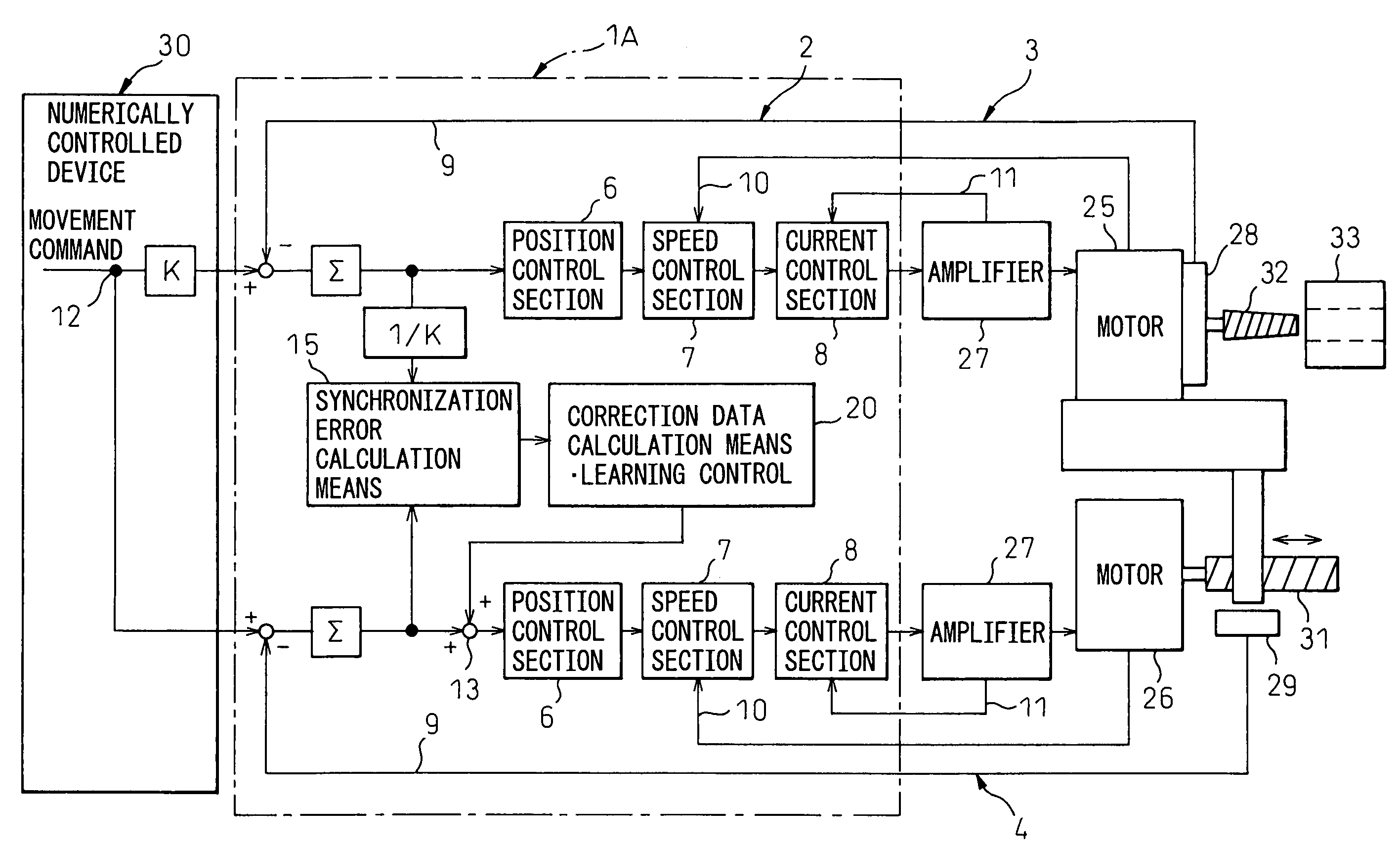
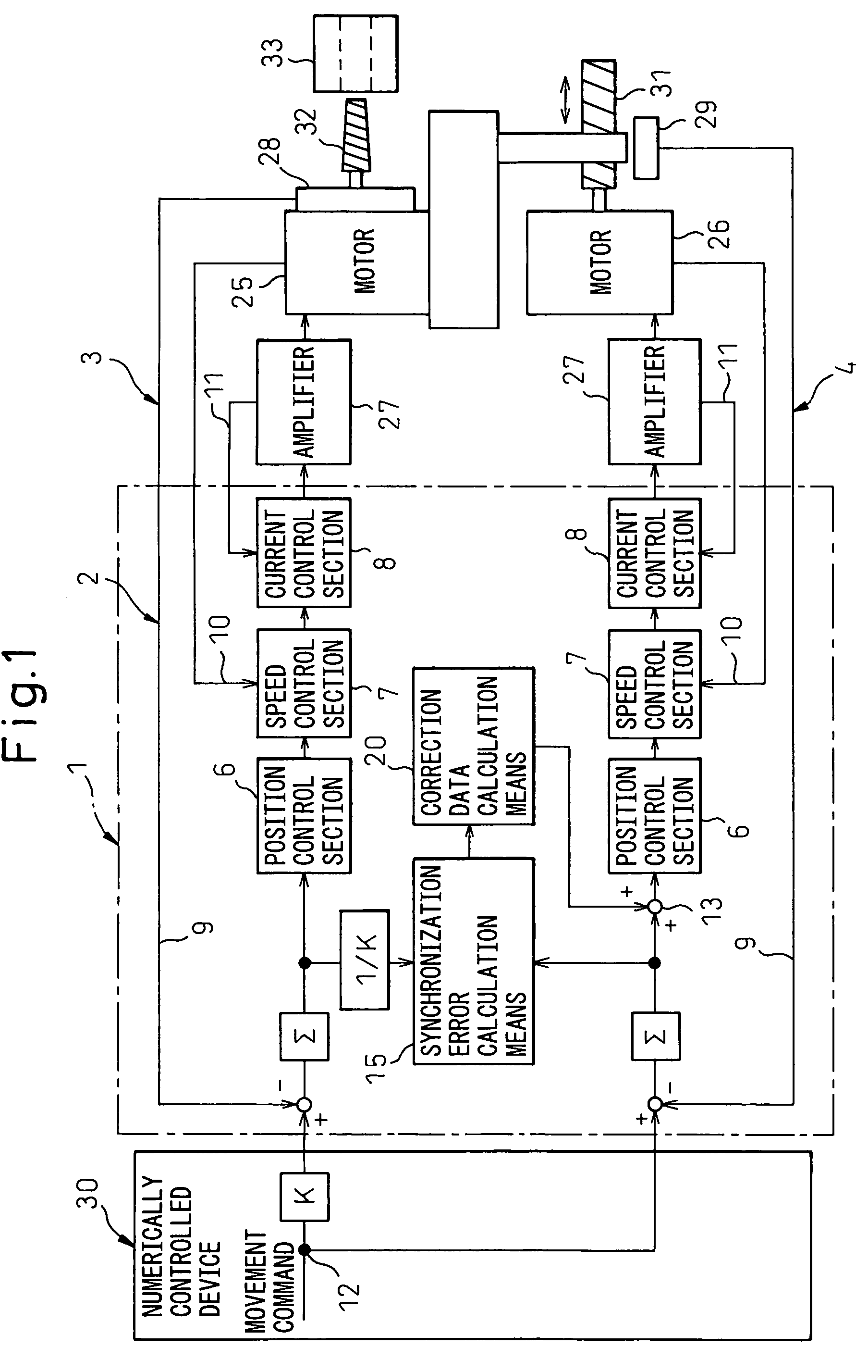
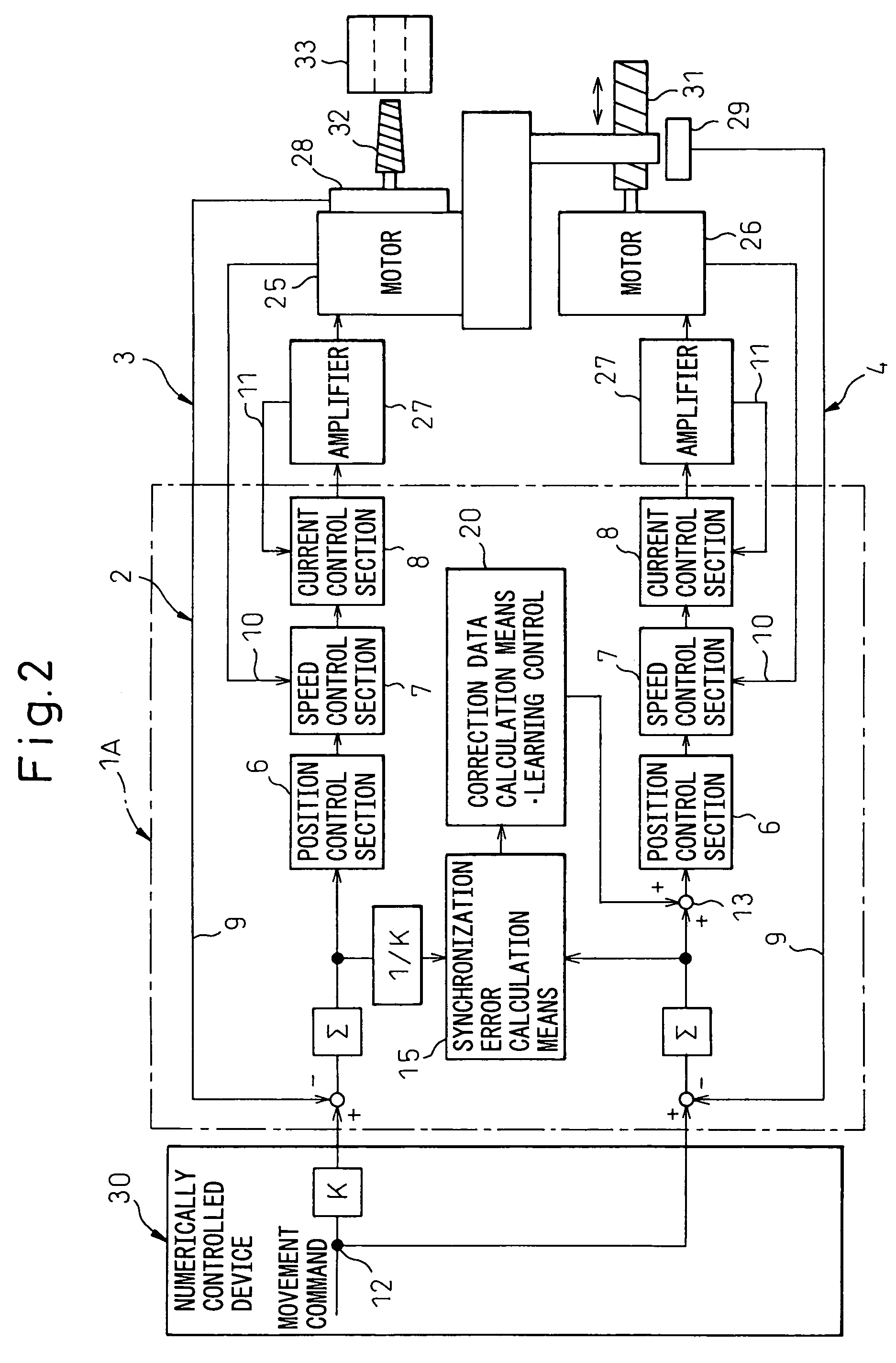
There is provided a servo controller for synchronously controlling a master side drive source to drive one drive axis and a slave side drive source to drive the other drive axis. The servo controller includes a correction data calculation means for calculating correction data to correct a positional deviation of a slave side drive source according to a synchronization error which is a difference between a positional deviation of a master side drive source and a positional deviation of the slave side drive source, in which the correction data is added to the positional deviation of the slave side drive source.

Description

BACKGROUND OF THE INVENTION[0001]1. Field of the Invention[0002]The present invention relates to a servo controller for synchronously controlling a master side drive source and a slave side drive source when the servo controller is applied to a machine in which the same machining is repeatedly conducted and, for example, thread cutting or tapping is repeatedly conducted.[0003]2. Description of the Related Art[0004]In general, in the case of machining a male screw on an outer circumferential face of a work, while the work chucked by a primary spindle is being rotated, a predetermined depth of cut is given to a thread cutting tool and the thread cutting tool is linearly moved in the axial direction of the work so as to conduct thread cutting on the work. In this case, in order to prevent the cutting tool from being given an excessively strong cutting force, the depth of cut is given to the cutting tool being divided by several times, that is, cutting of a predetermined depth is repeat...

Claims


Application Information

Patent Timeline
Patent Type & Authority Patents(United States)
IPC IPC(8): H02P5/46B23Q15/00
CPCG05B19/195G05B19/4141
Inventor IWASHITA, YASUSUKETOYOZAWA, YUKIOMAEDA, KAZUOMI
Owner FANUC LTD
Learn More