Earthing and overvoltage protection arrangement

a protection arrangement and overvoltage technology, applied in the direction of overvoltage protection resistors, emergency protection arrangements for limiting excess voltage/current, and arrangements responsive to excess voltage, etc., can solve the problems of large size and high price of transformers, heavy transformers and their electric connections may become detached from printed circuit boards, and signal and power supply components suitable for selv interface of conventional floating solutions are expensive or not available at all

Inactive Publication Date: 2010-02-02
ABB OY
View PDF12 Cites 29 Cited by
  • Summary
  • Abstract
  • Description
  • Claims
  • Application Information

AI Technical Summary

Benefits of technology

[0035]Though exemplary embodiments are described herein, it must be understood that a person skilled in the art will be able to apply the present invention in different forms within the limits specified by the claims, for example in connection with direct-current circuits.

Problems solved by technology

The large size and high price of the transformer are disadvantages.
In applications susceptible to vibration, the heavy transformer and its electric connections may become detached from the printed circuit board.
In practice, solutions employing resistive voltage division have been common in three-phase networks having a voltage of no more than 400 V, as the power loss in the voltage division resistors and the dielectric strength required of the isolation transformers have led to large-size solutions.
In connection with the design of power distribution system equipment for the “Overvoltage Category III” or higher, and environments with “Pollution Degree III”, the requirements for creepage and clearance distances mean that signal and power supply components suitable for the SELV interface of conventional floating solutions are expensive or not available at all.
If surge voltage or another type of spurious voltage increases the potential of the floating neutral point (COM) in relation to the protective earth (PE), the reverse breakdown voltage of the diode is exceeded and the resulting avalanche breakdown causes a flow of current.
The voltage will not be able to increase to a level that would exceed the dielectric strength of the components between the measurement electronics and the SELV circuit.
However, the price and size of these replacement components can be less advantageous compared to the diode arrangement.

Method used


Image

  • Earthing and overvoltage protection arrangement
  • Earthing and overvoltage protection arrangement
  • Earthing and overvoltage protection arrangement

Examples


Embodiment Construction

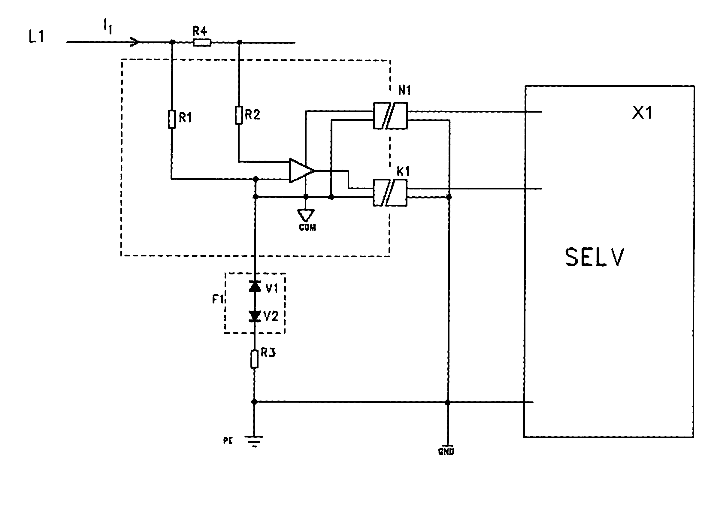
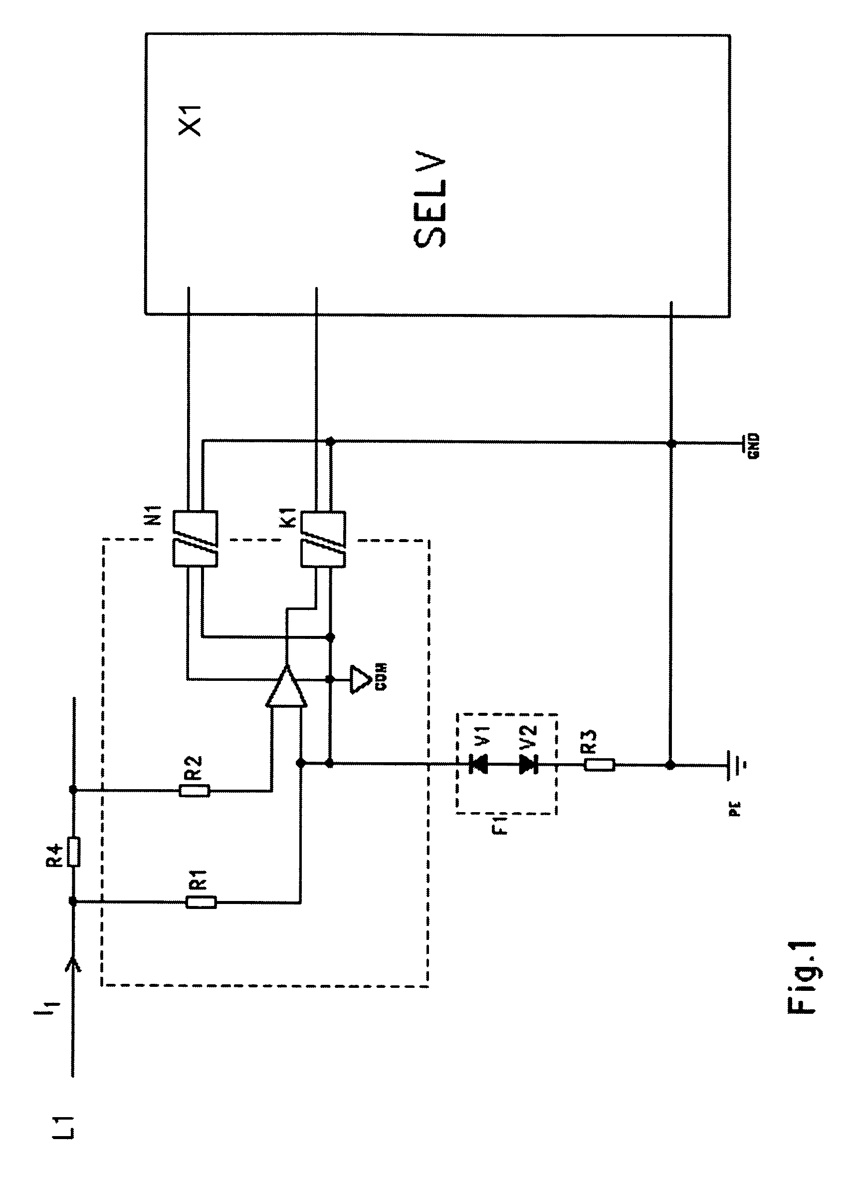
[0015]FIG. 1 illustrates an exemplary arrangement in connection with single-phase current measurement. The circuit under measurement includes a low (typically 1 . . . 100 mΩ, or lesser or greater) series resistance (R4), and the current (I1) in the circuit is determined on the basis of Ohm's Law by measuring the voltage drop across the resistance. The input of the measurement electronic circuit includes high resistances (R1, R2), typically 10 MΩ.

[0016]The artificial neutral point (COM) of the measurement electronics part, separated by a dashed line in the figure, is connected to the potential of the live conductor through one of the resistances (R1). Power supply to the measurement electronics can be arranged from the SELV electronic circuit (X1) using a DC / DC converter (N1) with sufficient dielectric strength, for example 3 kV.

[0017]The measurement result is either transmitted in analogue form through an opto-isolator (K1) to the SELV electronic circuit or, alternatively, the analo...


PUM


Abstract

An earthing of an electronic circuit is disclosed in a device belonging to a low-voltage system with, for example, a maximum AC voltage of 1000 V or a maximum DC voltage of 1500 V in which the device is at the main voltage potential or is connected to the main voltage through a high-impedance coupling. An overvoltage protection of the interface between such an electronic circuit and a SELV (Safety Extra Low Voltage) circuit is also disclosed. The neutral point (COM) of the electronic device is coupled to protective earth (PE) through at least one breakdown-based overvoltage protector. The rated breakdown voltage of the overvoltage protector is higher than the voltage present across it in normal operating conditions but lower than the minimum dielectric strength of the component forming the interface between the electronic device and the SELV circuit.

Description

CROSS-REFERENCE TO RELATED PATENT APPLICATIONS[0001]This application is based on and claims priority under 35 U.S.C. §119 to Finnish Application No. 20040695, filed May 18, 2004 and is a continuation application under 35 U.S.C. §120 of International Application No. PCT / FI2005 / 000222, filed May 17, 2005 designating the U.S., the entire contents of both of which are hereby incorporated by reference.FIELD[0002]Grounding is disclosed of an electronic circuit in a device belonging to a low-voltage system with a maximum AC voltage of, for example, 1000 V or a maximum DC voltage of, for example, 1500 V in which the device is at the main voltage potential or is connected to the main voltage through a high-impedance coupling, as well as to the overvoltage protection of the interface between such an electronic circuit and a SELV (Safety Extra Low Voltage) circuit.[0003]Examples of such electronic devices include instruments for measuring electrical quantities such as voltage, current or frequ...

Claims


Application Information

Patent Timeline
Patent Type & Authority Patents(United States)
IPC IPC(8): H02H3/22G01R1/36H02HH02H9/04
CPCG01R1/36H02H9/04
Inventor LAAKSO, KARI-MATTIBERTS, ANDREASKUIVALAINEN, JANNE
Owner ABB OY
Why Eureka
Try Eureka