Method of aligning probe for eddy current inspection

a technology of eddy current and alignment template, which is applied in the direction of mechanical means, mechanical roughness/irregularity measurements, liquid/fluent solid measurements, etc., can solve the problems of preventing the probe from being positioned at a uniform distance from the component, the procedure for aligning the probe for inspection is time-consuming, and the small coil is extremely sensitive to the inspection equipment. , to achieve the effect of reducing errors, eliminating alignment templates, and reducing errors

a technology of eddy current and alignment template, which is applied in the direction of mechanical means, mechanical roughness/irregularity measurements, liquid/fluent solid measurements, etc., can solve the problems of preventing the probe from being positioned at a uniform distance from the component, the procedure for aligning the probe for inspection is time-consuming, and the small coil is extremely sensitive to the inspection equipment. , to achieve the effect of reducing errors, eliminating alignment templates, and reducing errors

US7657389B2Active Publication Date: 2010-02-02GENERAL ELECTRIC CO

Image

  • Method of aligning probe for eddy current inspection
  • Method of aligning probe for eddy current inspection
  • Method of aligning probe for eddy current inspection

Examples


Embodiment Construction

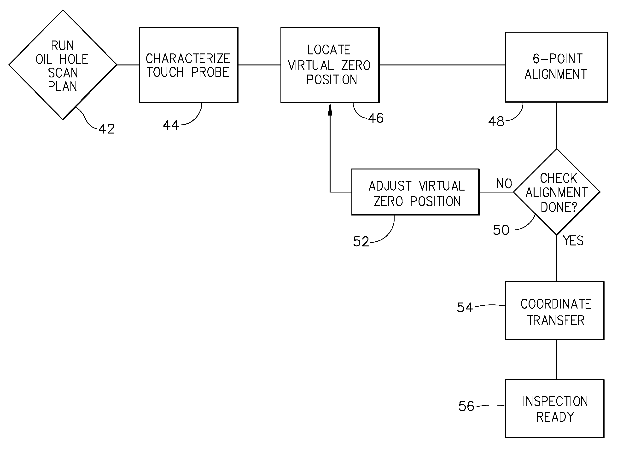
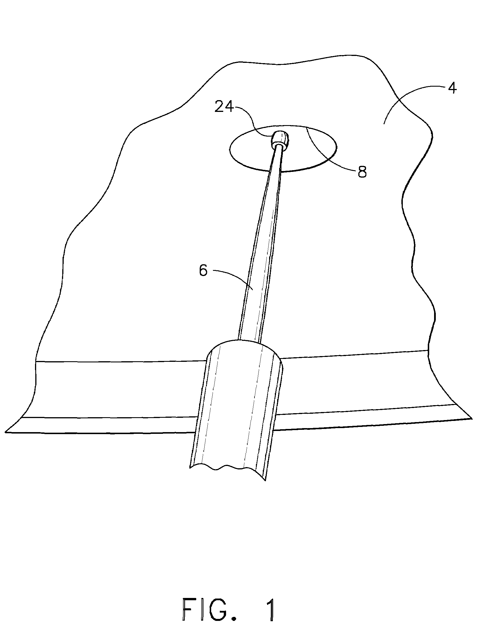
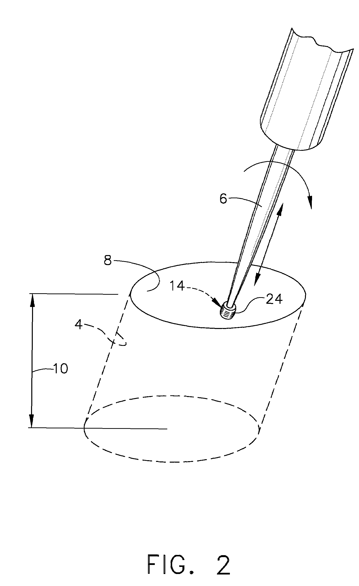
[0029]A touch probe is used to align the EC probe for eddy current inspection of manufactured components such as gas turbine engine components. FIG. 1 illustrates the eddy current inspection of an oil drain hole 8 of a component. While FIG. 1 is shown and described as the feature being inspected, any feature or surface requiring inspection may be utilized. The eddy current probe 6 is placed inside the oil drain hole 8 as shown in FIG. 2, or near the component for inspection. An alternating current through the probe coil 14 (not shown) produces eddy currents in the component surface 4. The reaction of the eddy currents in the component surface 4 are monitored by the probe 6 and are sent to a computer to process. Before the inspection can be initiated, however, several steps must be performed by using a touch probe to correctly align the eddy current probe 6 to ensure accurate results. Lift-off, the gap between the EC probe 6 and the component surface 4, must be eliminated during insp...


PUM


Abstract

A system and method using a touch probe device for eddy current inspection. The touch probe provides a simple approach for coming within close contact of the specimen while maintaining a normal angle and pressure at the right positions. The use of the touch probe further reduces the total time for the eddy current inspection. The touch probe aligns the probe to a specimen to be inspected, for the purpose of reducing measurement errors and increasing productivity.

Description

CROSS REFERENCE TO RELATED APPLICATIONS[0001]This application claims the benefit of expired Provisional Application No. 60 / 744,693 filed Apr. 12, 2006, the complete disclosure of which is incorporated herein by reference.FIELD OF THE INVENTION[0002]The present invention is directed to a method of automatic alignment for eddy current inspection using a Touch probe (TP).BACKGROUND OF THE INVENTION[0003]Eddy current (EC) inspection is commonly used to detect flaws in material properties such as residual stress, density, and degrees of heat treatment, as well as detect any cracks, pings, dings, or raised material on surfaces of manufactured components such as gas turbine engine components. EC inspection is required for most aircraft engine components on which abnormal indications are detected to ensure the engine's integrity until the next maintenance schedule. During this type of inspection, electromagnetic induction is used to induce eddy currents in the component being inspected. An ...

Claims


Application Information

Patent Timeline
02 Feb 2010
Publication
US7657389B2
IPC
G01D18/00; G06F17/40; G06F19/00
CPC
G01N27/9006
Inventors
SUH, UI W.; KNEPFLE, RICHARD C.