Tri-to-hex light mixing and homogenizing apparatus and method

a technology of tri-hex light and homogenizing apparatus, which is applied in the direction of waveguide type devices, lighting and heating apparatus, instruments, etc., can solve the problems of limiting the application of this useful technique, increasing the cost and weight of the optical system, and achieving the elimination of alignment problems and manufacturing more economically.

Inactive Publication Date: 2007-01-18
THE BOEING CO
View PDF30 Cites 2 Cited by
  • Summary
  • Abstract
  • Description
  • Claims
  • Application Information

AI Technical Summary

Benefits of technology

[0006] The present disclosure teaches structures and methods that fulfill long felt needs in the industry by producing a mixed and homogenized light beam from a plurality of incoming light beams, where each of the incoming light beams has a non-uniform, gaussian intensity distribution. In particular, the structures and methods disclosed have particular application to diverse technology areas including optical components, entertainment, mass communications, interior / exterior aircraft lighting, and aircraft runway lighting. The disclosed structure is beneficial because it does not include a traditional, filled optical cavity or optical components such as beam splitters, and thus may be manufactured more economically. Additionally, the disclosed structure is rugged and may be used in applications that may receive physical shock. Since no additional optical components are needed, alignment issues are eliminated.

Problems solved by technology

Optical devices that mix two or more incoming light beams are known, yet such devices typically include heavy, expensive, and delicate components which limit the application of this useful technique.
Further, since the incoming light beams typically have a Gaussian, non-uniform intensity distribution, additional components are typically required to produce a uniform intensity distribution.
Such additional components contribute to the increased cost and weight of the optical system.

Method used


Image

  • Tri-to-hex light mixing and homogenizing apparatus and method
  • Tri-to-hex light mixing and homogenizing apparatus and method
  • Tri-to-hex light mixing and homogenizing apparatus and method

Examples


Embodiment Construction

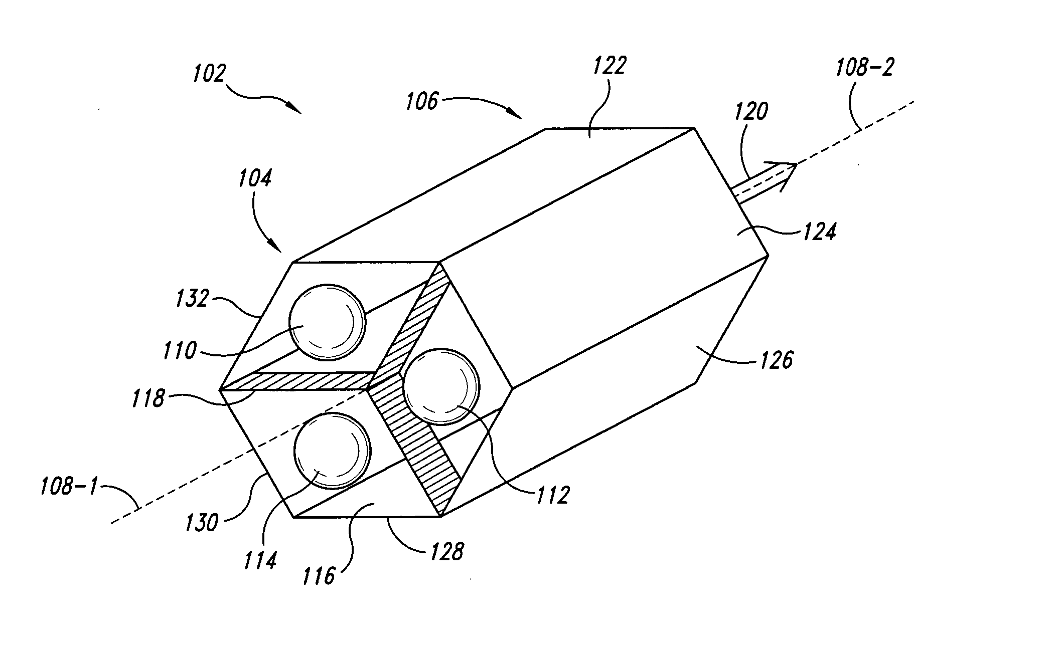
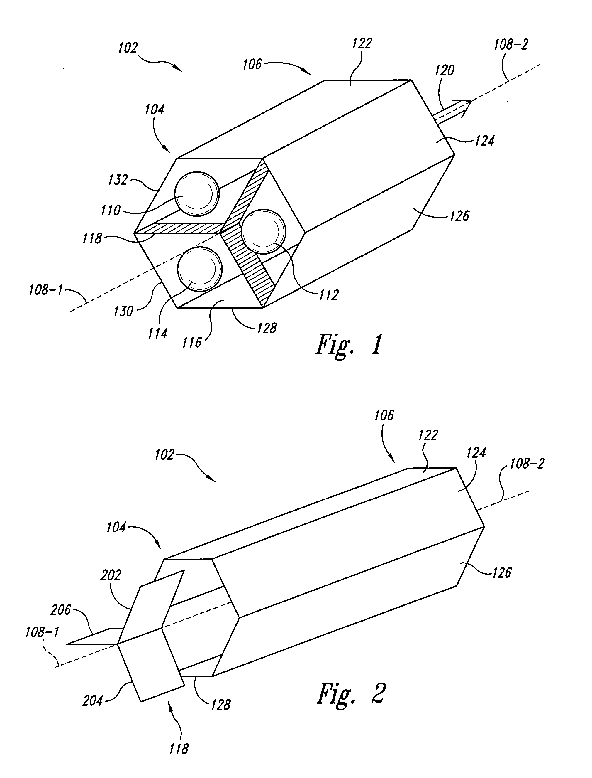
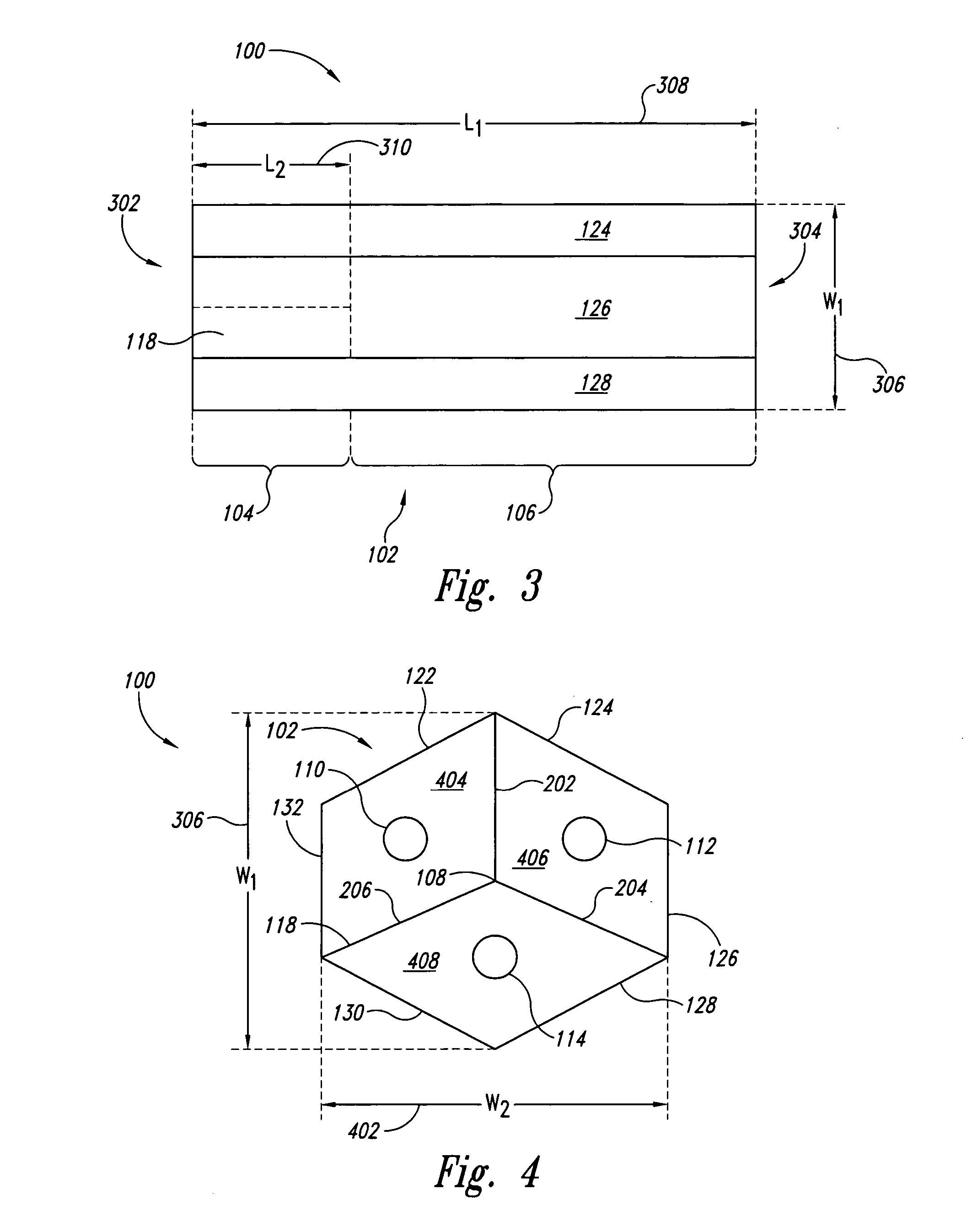
[0020] In reference to FIG. 1, an embodiment of a light mixing and homogenizing apparatus 100 includes a tubular member or body 102 having a hexagonal cross-section with a first end portion 104 and a second end portion 106. Both first end portion 104 and second end portion 106 are arranged about a central, longitudinal axis 108 so that the geometric cross-section for each end portion (104, 106) extends symmetrically in the direction of longitudinal axis 108 forming sides of the end portions (104, 106).

[0021] In this disclosure, longitudinal axis 108 can include a central line passing symmetrically through the long or axial direction of tubular member 102 equidistant from each side member in first end portion 104 and second end portion 106. First end portion 104 can receive a plurality of incoming light beams (110, 112, 114), each incoming light beam has a Gaussian distribution where the intensity at the center of the incoming beam is higher than near the edges. Tubular member 102 h...


PUM


Abstract

In accordance with an embodiment, a light mixing and homogenizing apparatus includes a tubular member and a dividing member. The tubular member has a reflective interior surface and a polygonal cross section. The tubular member has a first end configured to receive a plurality of incoming light beams and a second end configured to output mixed and homogenized light from the plurality of incoming light beams. The dividing member has a reflective surface and is located within the tubular member first end. The dividing member is configured to separate the plurality of incoming light beams from each other prior to mixing.

Description

TECHNICAL FIELD [0001] The present invention relates generally to optical guides, and more particularly to an optical apparatus for mixing and homogenizing up to three input light beams having non-uniform intensity profiles and producing a single, uniform intensity output. RELATED ART [0002] Optical devices that mix two or more incoming light beams are known, yet such devices typically include heavy, expensive, and delicate components which limit the application of this useful technique. Further, since the incoming light beams typically have a Gaussian, non-uniform intensity distribution, additional components are typically required to produce a uniform intensity distribution. Such additional components contribute to the increased cost and weight of the optical system. Thus, there remains a need for an apparatus and method to produce a mixed and homogenized output light beam from a plurality of non-homogenous incoming light beams in a rugged, compact, and low cost manner. SUMMARY [0...

Claims


Application Information

Patent Timeline
Patent Type & Authority Applications(United States)
IPC IPC(8): G02B5/02
CPCG02B6/0096G02B27/0977G02B27/0905G02B6/2808
Inventor CIANCIOTTO, FRANK T.
Owner THE BOEING CO
Why Eureka
Try Eureka