Cartridge insert for a fluid line

a technology of fluid line and insert, which is applied in the direction of fluid pressure control, water supply installation, functional valve types, etc., can solve the problems of not always being able to accommodate, and achieve the effect of reducing the control gap, promoting low manufacturing cost, and reliable and disturbance-free functioning of backflow inhibitors

Inactive Publication Date: 2005-01-04
NEOPERL
View PDF4 Cites 61 Cited by
  • Summary
  • Abstract
  • Description
  • Claims
  • Application Information

AI Technical Summary

Benefits of technology

The object therefore arises in particular of creating a cartridge insert of the type noted above that can be manufactured economically and that has, due to its compact design, a low space requirement for installation, so that for example, connections in series with additional insert parts are also possible, without using spacing elements.
The cartridge insert according to the present invention, and the individual parts thereof, can be manufactured from any suitable materials. However, in order to further promote the low manufacturing cost, it is advantageous if the cartridge housing, which may be made up of a multiplicity of parts, and / or the closing element are made of plastic and are injection-molded parts.

Problems solved by technology

Because the comparatively thick regulator core in this known cartridge insert protrudes past the end opening thereof, it is not always possible to accommodate the cartridge insert in the connection fitting of a water line without problems.

Method used


Image

  • Cartridge insert for a fluid line
  • Cartridge insert for a fluid line
  • Cartridge insert for a fluid line

Examples


Embodiment Construction

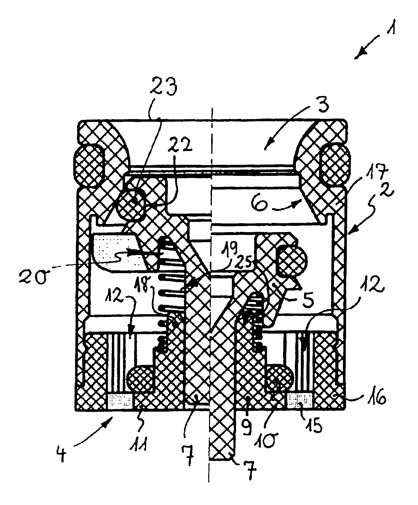
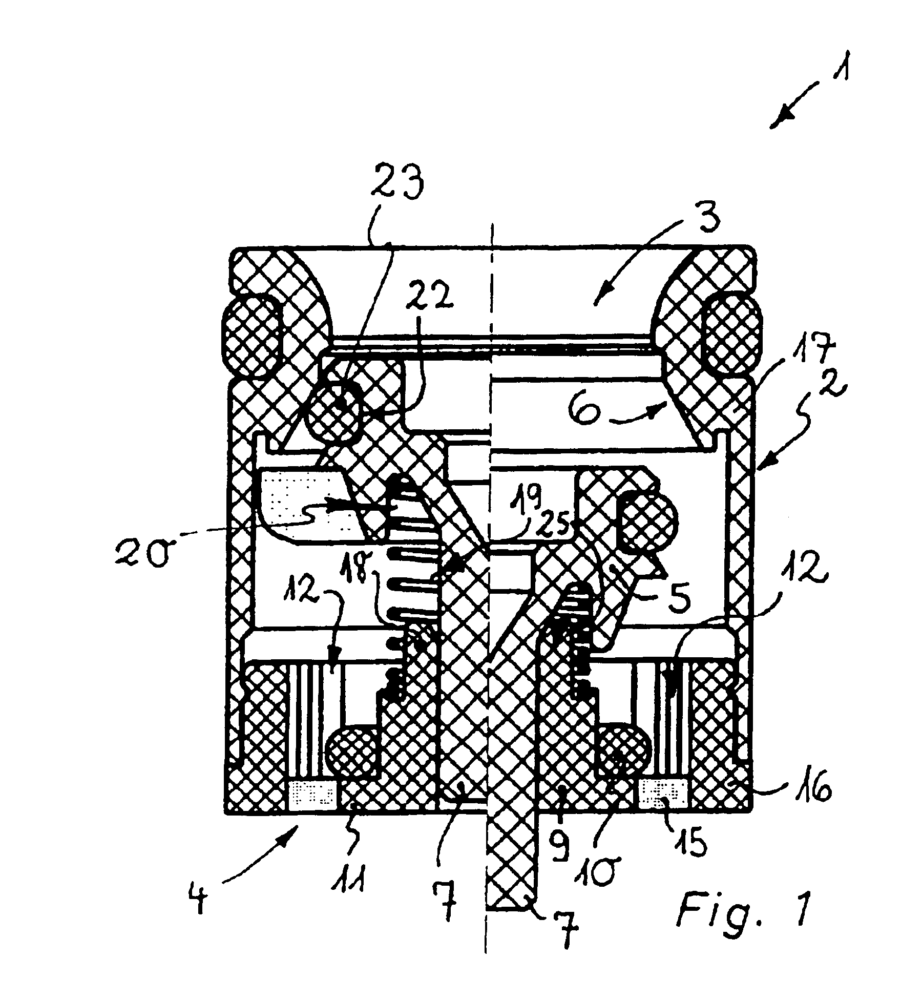
In FIGS. 1 to 3, a cartridge insert 1 is shown that can be placed into a corresponding recess in a connecting fitting of a sanitary water line. The cartridge insert 1 has in its cartridge housing 2 a backflow inhibitor 3 and a flow regulator 4 situated downstream. While the backflow inhibitor 3 is intended to prevent an undesired backflow of the liquid stream opposite to the standard direction of flow, with the aid of the flow regulator 4 the flow rate of the stream of water passing through the cartridge insert 1 is defined at a target value per time unit.

The backflow inhibitor 3 has a closing element 5 that lies tightly on a valve seat 6 of the cartridge housing 2 in the closed position shown in the left half of FIG. 1, and can be moved against a return force from this closed position into an open position, shown in the right half of FIG. 1.

From FIG. 1, it can be seen clearly that a downstream guide pin 7 protrudes from the closing element 5 of the backflow inhibitor 3, said pin be...


PUM


Abstract

A cartridge insert for insertion in a fluid line is provided having a cartridge housing within which is located at least one backflow inhibitor and downstream at least one flow regulator. The backflow inhibitor has a closing element, which, in a closed position thereof, lies tightly sealed on a valve seat of the cartridge housing and which may be displaced from the closed position against a return force into an open position. A downstream guide pin projects from the closing element, and extends into a guide opening of a central regulator core of the flow regulator, and the flow regulator is formed from a regulator element made from an elastic material that surrounds the regulator core, which rests on an annular shoulder and defines a control gap, which changes with pressure between the above and an opposing enclosing wall. The cartridge insert is compact and space saving in that the flow regulator terminates generally flush with the downstream side of the cartridge and the annular shoulder projects from the regulator core and the control gap is provided between the regulating element and an inside of the cartridge housing which forms the enclosing wall.

Description

BACKGROUNDThe present invention relates to a cartridge insert for insertion in a fluid line, having in its cartridge housing at least one backflow inhibitor and, downstream, at least one flow regulator. The backflow inhibitor has a closing element that in its closed position lies tightly on a valve seat of the cartridge housing and can be moved from this closed position against a return force into an open position. A guide pin, situated downstream, protrudes from the closing element and is guided in the guide opening of a central regulator core of the flow regulator. The flow regulator has a regulator element, made of elastic material, that surrounds the regulator core and that lies on an annular shoulder or on a similar regulator element support element, and that limits, between itself and an enclosing wall situated opposite, a control gap that changes in a manner dependent on pressure.Cartridge inserts of this sort are used for example in sanitary water lines in order to prevent a...

Claims


Application Information

Patent Timeline
Patent Type & Authority Patents(United States)
IPC IPC(8): G05D7/01G05D7/00
CPCG05D7/012F16K15/063F16K15/142Y10T137/5109Y10T137/7932Y10T137/87917
Inventor WEIS, CHRISTOPHZOLLER, UWE
Owner NEOPERL
Why Eureka
Try Eureka