Display device

a display device and display technology, applied in the field of display devices, can solve the problems of limited miniaturization of these light sources and substantial heat loss, and achieve the effects of low heat emission, small installation space, and high light efficiency

Inactive Publication Date: 2006-10-31
SIEMENS AG
View PDF13 Cites 37 Cited by
  • Summary
  • Abstract
  • Description
  • Claims
  • Application Information

AI Technical Summary

Benefits of technology

[0008]It is therefore the object of the invention to configure a display device of the type mentioned at the beginning such that the light emitted by the individual light sources is available for illuminating the display in a way as free as possible from losses.
[0009]This object is achieved according to the invention by virtue of the fact that either the light guide has individual light guiding sections that are assigned to the individual light sources on the light source side and which merge on the display side into a common light guiding section, or in that the light guide has convex lens elements on its light entrance side facing the light source and on its light exit side facing the display, the individual light sources respectively being assigned a convex lens element, corresponding to a convex lens element on the light exit side, on the light entrance side. Light losses can therefore be avoided as far as possible in a simple way. In the case of the second solution, the light is guided between the convex lens elements on the light entrance side and those on the light exit side of the light guide the light is in a fashion focussed by the first-mentioned lens elements and avoiding scattering losses. The display device according to the invention also has a very low space requirement and permits the use of any desired light sources. The power efficiency of the device is very high, and there is no need for an additional cooling device even in the case of a restricted installation in the dashboard of a motor vehicle.
[0010]A further increase in the light efficiency is achieved by an embodiment of the display device according to the invention, in which the emission angle of the light emerging from the light guide is exactly equal to or less than the emission angle of the light radiated by the light source. In this way, the light is not only led with low losses in the light guide from the light source to the display, but is focussed in addition at the same time in a fashion that increases intensity.

Problems solved by technology

Because of the constricted space conditions generally applying in the region of the dashboard of the motor vehicle in which the display device is fitted, and of the therefore problematic use of intense light sources that, firstly, require a large installation space and, secondly, emit a substantial heat loss, an attempt is being made to replace the individual light source by a plurality of light sources that admittedly each have a low light intensity per se, but which also have a low heat loss emission.
The problem arises in this case that because of geometric boundary conditions—the miniaturization of these light sources is limited—the arrangement of light sources requires a larger surface than that to be illuminated.
Again, there are disadvantageous light losses owing to the exit of light at the side surfaces of the light guide, since the light beams impinge on the surface on each reflection at a relatively large angle near the perpendicular, and the total reflection is thereby cancelled.

Method used


Image

  • Display device
  • Display device
  • Display device

Examples


first embodiment

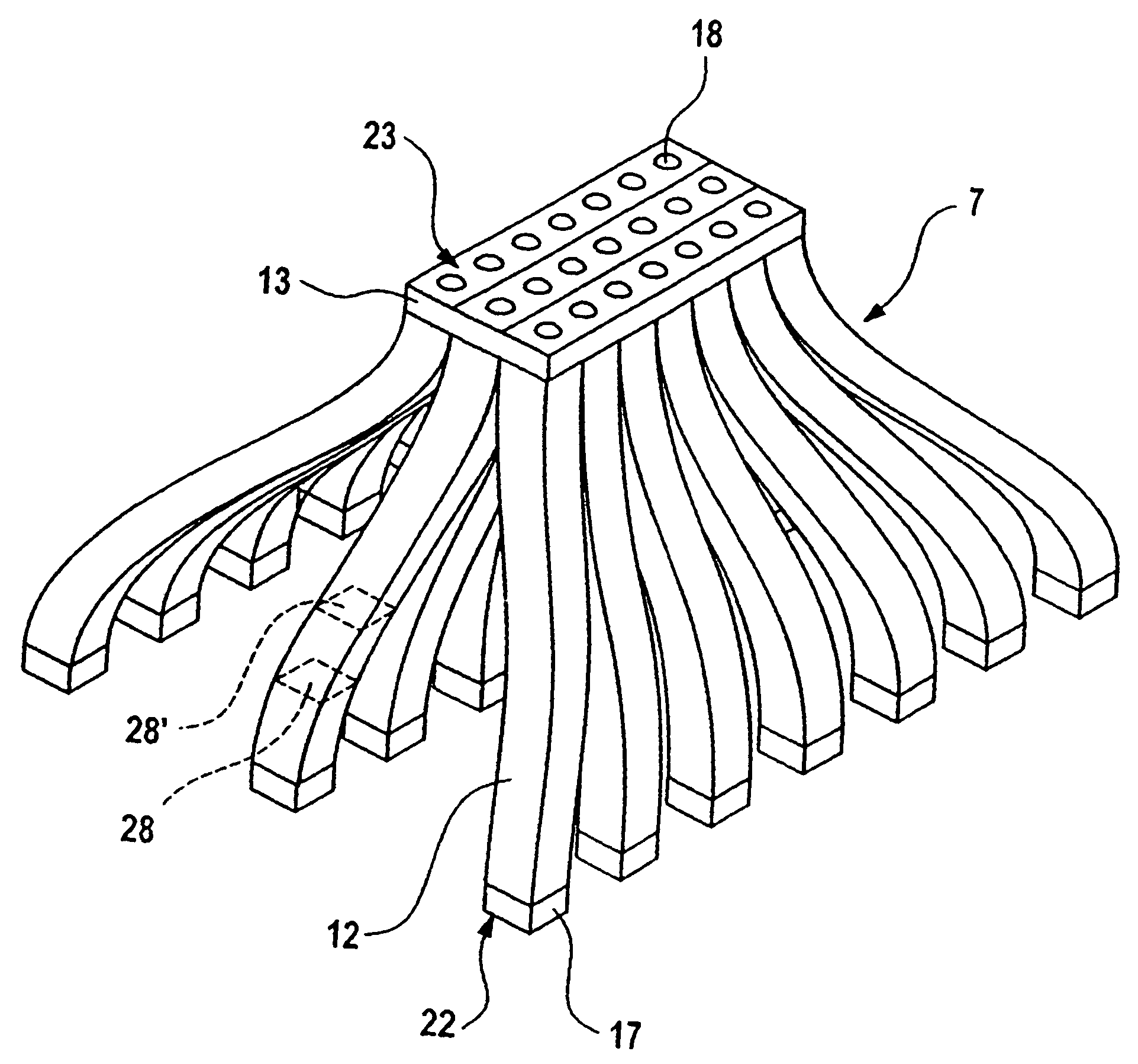
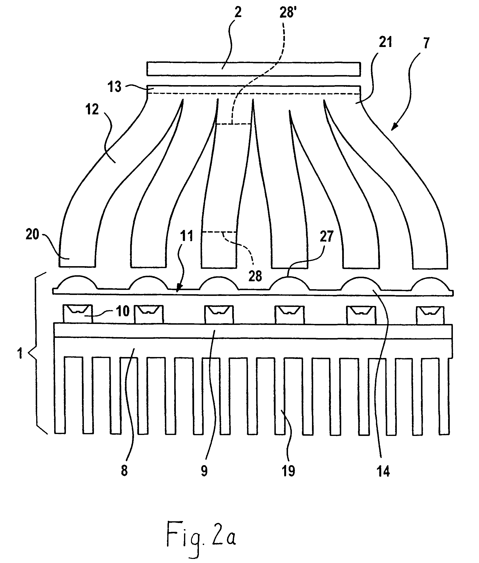
[0037]The particulars of a detail of a display device in a first embodiment are shown in FIG. 2a. It is to be seen here that a display 2 formed by an LCD can be illuminated by a light source 1 via an injection-molded light guide 7 made from transparent, light-guiding plastic. The light source 1 has a printed circuit board 9 on the front side of which, facing the light guide 7, a number of individual light sources 10 are arranged and fastened and make electric contact. The individual light sources 10 are formed by LEDs, and the overall light-emitting surface of the individual light sources 10 is greater than the surface of the display 2. On its rear side, the printed circuit board 9 is provided with a cooling element 8, having cooling ribs 19, for dissipating the heat produced by the light sources 10.

[0038]The light guide 7 has individual light guiding sections 12 constructed as fingers with cross-sectional areas 28, 28′. The cross sectional areas 28, 28′ of each of the individual li...

second embodiment

[0043]Particulars of a detail of a display device in the second embodiment are shown in FIG. 6a. Here, a display 2 formed by a transilluminable LCD can be illuminated by a light source 1 via a light guide 57 made from transparent, light-guiding plastic. The light source 1 has a printed circuit board 59 on the front side of which, facing the light guide 57, a number of individual light sources 60 are arranged and fastened and make electric contact. The individual light sources 60 are formed by LEDs, and the overall light-emitting surface of the individual light sources 60 is greater than the surface of the display 2. On its rear side, the printed circuit board 59 is provided with a cooling element 58, having cooling ribs 70, for dissipating the heat produced by the light sources 60. Moreover, the printed circuit board 59 itself has a high thermal conductivity, and thus contributes to the dissipation of heat.

[0044]The light guide 57 has convex lens elements 61 on its light entrance si...


PUM

PropertyMeasurementUnit
emission angleaaaaaaaaaa
thermal conductivityaaaaaaaaaa
heataaaaaaaaaa

Abstract

The invention relates to a display device, especially in a motor vehicle, comprising a display (2) which can be illuminated by a light source (1), and a light guide (7) which is arranged between the light source (1) and the display (2). Said light source (1) comprises a plurality of individual light sources (10), the entire light-radiating surface of said light sources being larger than the surface of the display (2). In order to increase the light efficiency, the light guide (7) comprises, on the light source side, individual light guiding sections (12) which are associated with the individual light sources (10), said sections forming a common light guiding section (13) on the display side.

Description

PRIORITY CLAIM[0001]This is a U.S. national stage of application No. PCT / DE02 / 03721, filed on Oct. 1, 2002. Priority is claimed on that application and on the following application: Country: Germany, Application No.: 101 49 836.5, Filed: Oct. 10, 2001.BACKGROUND OF THE INVENTION[0002]1. Field of the Invention[0003]The invention relates to a display device, in particular in a motor vehicle, having a display that can be illuminated by a light source, and a light guide arranged between the light source and display, the light source having several individual light sources whose overall light-emitting surface is larger than the surface of the display.[0004]2. Description of the Prior Art[0005]Such display devices are known, and are used, for example in motor vehicles for instrument illumination. By contrast with displays that can be illuminated by intense individual light sources such as, for example, halogen lamps or fluorescent lamps, these devices can have a lower power consumption an...

Claims


Application Information

Patent Timeline
Patent Type & Authority Patents(United States)
IPC IPC(8): G01D11/28G02B6/00B60K35/00B60R11/02F21S2/00F21S8/04F21V8/00F21Y101/02G02B6/04G02B6/42G02B27/00G02B27/01G02F1/13G02F1/13357G09F9/00H01L33/00H01L33/58
CPCG02B6/04G02B6/4249G02B27/0101B60K2350/203G02B6/4201G02B2027/0118Y10S362/80G02B6/428G02B6/424G02B6/4244G02B6/4268B60K2370/33
Inventor LUDEWIG, BERNDMAYER, RALFNOLL, HEINRICH
Owner SIEMENS AG
Why Eureka
Try Eureka