Measuring device and method for spatial pose of rigid body

A technology of pose measurement and measurement device, applied in the field of measurement and control, can solve problems such as increased cost and poor real-time performance, and achieve the effects of improved measurement accuracy, low cost, and high system real-time performance

A technology of pose measurement and measurement device, applied in the field of measurement and control, can solve problems such as increased cost and poor real-time performance, and achieve the effects of improved measurement accuracy, low cost, and high system real-time performance

CN1570556AInactive Publication Date: 2005-01-26TSINGHUA UNIV +1

Image

  • Measuring device and method for spatial pose of rigid body
  • Measuring device and method for spatial pose of rigid body
  • Measuring device and method for spatial pose of rigid body

Examples


Embodiment Construction

[0033] The method and device for measuring the pose of a motion rigid body according to the present invention will be specifically described in conjunction with the accompanying drawings.

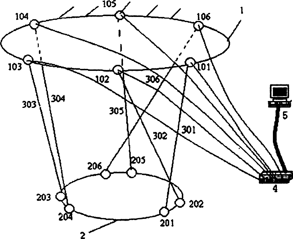
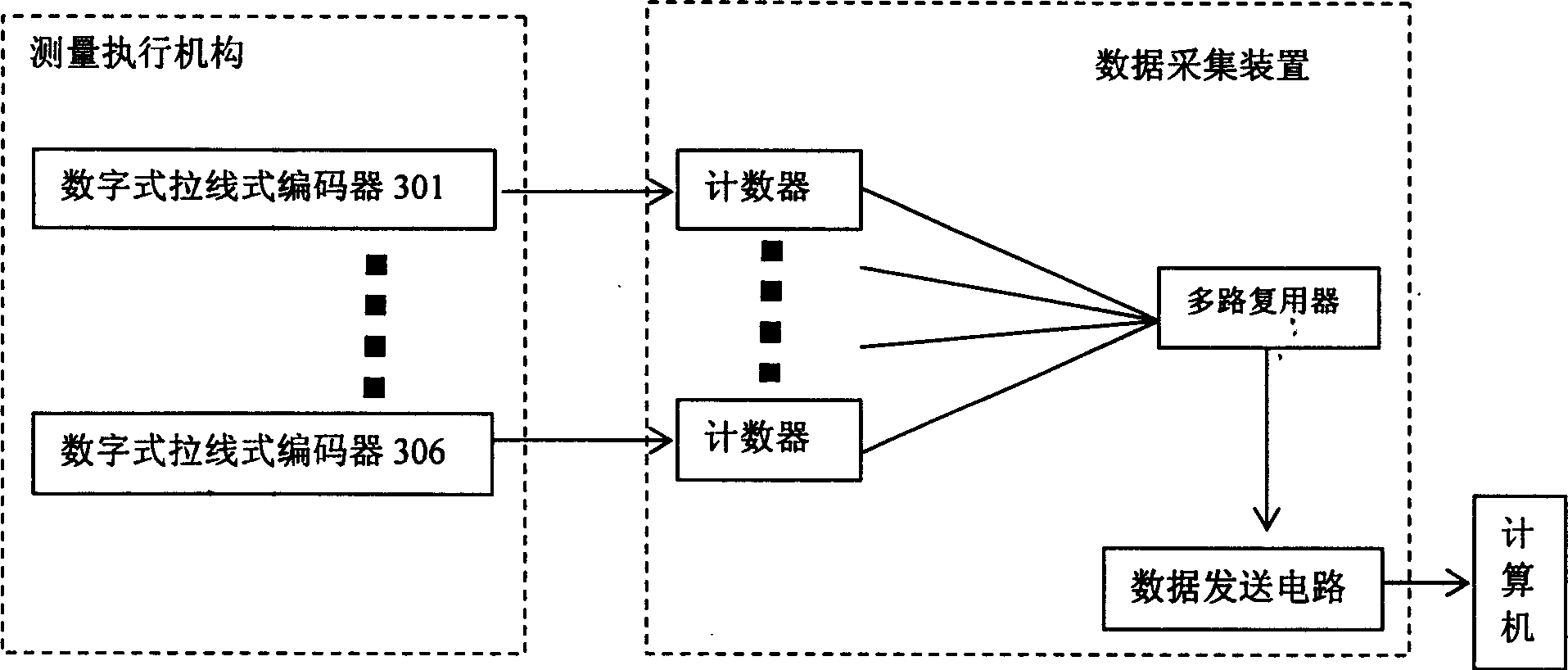
[0034] Such as figure 1 As mentioned above, the rigid body space pose measurement device of the present invention includes a measurement actuator, a data acquisition device, and a computer storing a calculation program; the measurement actuator includes a fixed platform 1, and six spherical joints 101- 106; motion platform 2, six ball hinges 201-206 installed on the motion platform; cable-pull encoders 301-306 correspondingly connecting ball hinges 101-106 and 201-206; The output end of the encoder is connected, and the output end of the data acquisition device 4 is connected with the corresponding input port of the computer 5 .

[0035] The fixed platform 1 is used to install six spherical joints 101-106, so that the position of the spherical joints is fixed, a fixed fixed platform coordi...


PUM


Abstract

It is the measuring apparatus and method for the space position of rigid body and belongs to the field of observation and control. The invention provides a contact measuring apparatus for space position of a rigid body of low cost and high accuracy, which comprises measuring execution structure, data-collecting apparatus and a computer capable of storing calculation programs. The invention also discloses a method for the measuring. The method is used to get space position information of the rigid body to be measured by the use of iterative equations set according to the initial datum obtained from the said apparatus. The said apparatus is characterized by simple structure and high system real-time capabilities and can realize the closed-loop real-time control of the rigid body to be measured.

Description

technical field [0001] The invention belongs to the technical field of measurement and control, and relates to a method and a device for measuring a six-degree-of-freedom pose in a rigid body space. Background technique [0002] In a Cartesian coordinate system, a rigid body has six degrees of freedom. In the industrial control of machine tools, mechanisms, robots, etc., in order to achieve high-precision positioning, the control usually adopts closed-loop feedback control, which puts forward requirements for the dynamic measurement of space pose. In the current closed-loop feedback control, there are two main measurement methods: measuring the displacement (or angular displacement) of the actuator joint for feedback or directly measuring the pose of the terminal for feedback. [0003] In the scheme of measuring the joint displacement (or angular displacement) of the actuator for feedback, it can be divided into two methods: semi-closed-loop feedback and full-closed-loop fe...

Claims


Application Information

Patent Timeline
26 Jan 2005
Publication
CN1570556A
IPC
B23Q17/22; G01B21/00
Inventors
段广洪; 张辉