Powershiftable multistage transmission

a transmission and multi-stage technology, applied in transmission elements, electric energy vehicles, toothed gearings, etc., can solve the problems of affecting the transmission efficiency of the transmission, the transmission can be switched six forward speeds, and the shifting of five shifting elements, etc., to achieve the effect of small total space requirement and high efficiency

Inactive Publication Date: 2010-10-26
EGS ENTWICKLUNGSGESELLSCHAFT FUR GETRIEBESYSTEME MBH
View PDF14 Cites 38 Cited by
  • Summary
  • Abstract
  • Description
  • Claims
  • Application Information

AI Technical Summary

Benefits of technology

[0011]A further object of the invention is to provide a powershiftable multistage transmission comprising a plurality of gear sets, namely three transfer gears and three planetary gears, and a plurality of shifting elements with which the powershiftings of an as large as possible number of forward speeds and at least one reverse speed is achieved with as few as possible shifting elements and which has a small total space requirement and achieves a high efficiency.
[0012]Another object is to provide a powershiftable multistage transmission with a short overall length by splitting up the gear structure on a plurality of shaft-lines.
[0024]It is an important advantage of a gear-structure with the arrangement of the gear elements on two shaft-lines that this leads to many more possible connections than in an inline-structure. This establishes more possible combinations of different connections for more gears which can be shifted with fewer shifting elements.
[0028]In the transmission according to the second preferred embodiment, the second shaft is firmly connected to the second planet-carrier and the second clutch can link the seventh shaft to the second sun gear. In the transmission according to the third preferred embodiment, the alternative second clutch can link the second shaft to the second planet carrier. But then the connection between the seventh shaft and the second sun gear is fixed. Shifting elements shift power paths through a gear-structure. For the total ratio of a gear it is insignificant, at which point a power-path is defined by a closed shifting element. Therefore the shifting elements can be arranged in that way at certain positions that they can be actuated easily and that they have low loads if they are closed and low relative speeds if they are open.
[0033]Of course further shifting elements can be implemented in the gear structures, which are described so far, to get more kinematic connections for more gears. One example of this is represented by a seventh preferred embodiment in that in the gear-structure according to the third preferred embodiment, an additional second brake can connect the second planet-carrier to the transmission housing. With this additional brake the transmissions get another reverse gear. This can be advantageous in some applications.

Problems solved by technology

A disadvantage of this transmission is that with this number of shifting elements only six forward speeds can be switched.
That means that only two of five shifting elements are sliding and creating some sliding losses in each gear.
This coaxial arrangement of four planetary gears is the reason why such a transmission becomes long and not very well suitable for front-cross-applications.
Furthermore the coaxial arrangement of the planetary gear sets on only one shaft-line leads to the disadvantage, that at some points of the transmission up to five shafts are running within each other.
That makes the arrangement of bearings complex.
Furthermore it is a disadvantage, that in no transmission, described in this paper, all clutches can be fed with oil from the housing only through one oil transmitter between parts with relative speed.
But to achieve much different ratio steppings the stationary ratios have to become too big or too small, so that the transmission design will become difficult.
But in the transmission structures, described in this state of the art, an electric motor can not be linked to the most suitable shaft.

Method used


Image

  • Powershiftable multistage transmission
  • Powershiftable multistage transmission
  • Powershiftable multistage transmission

Examples


Embodiment Construction

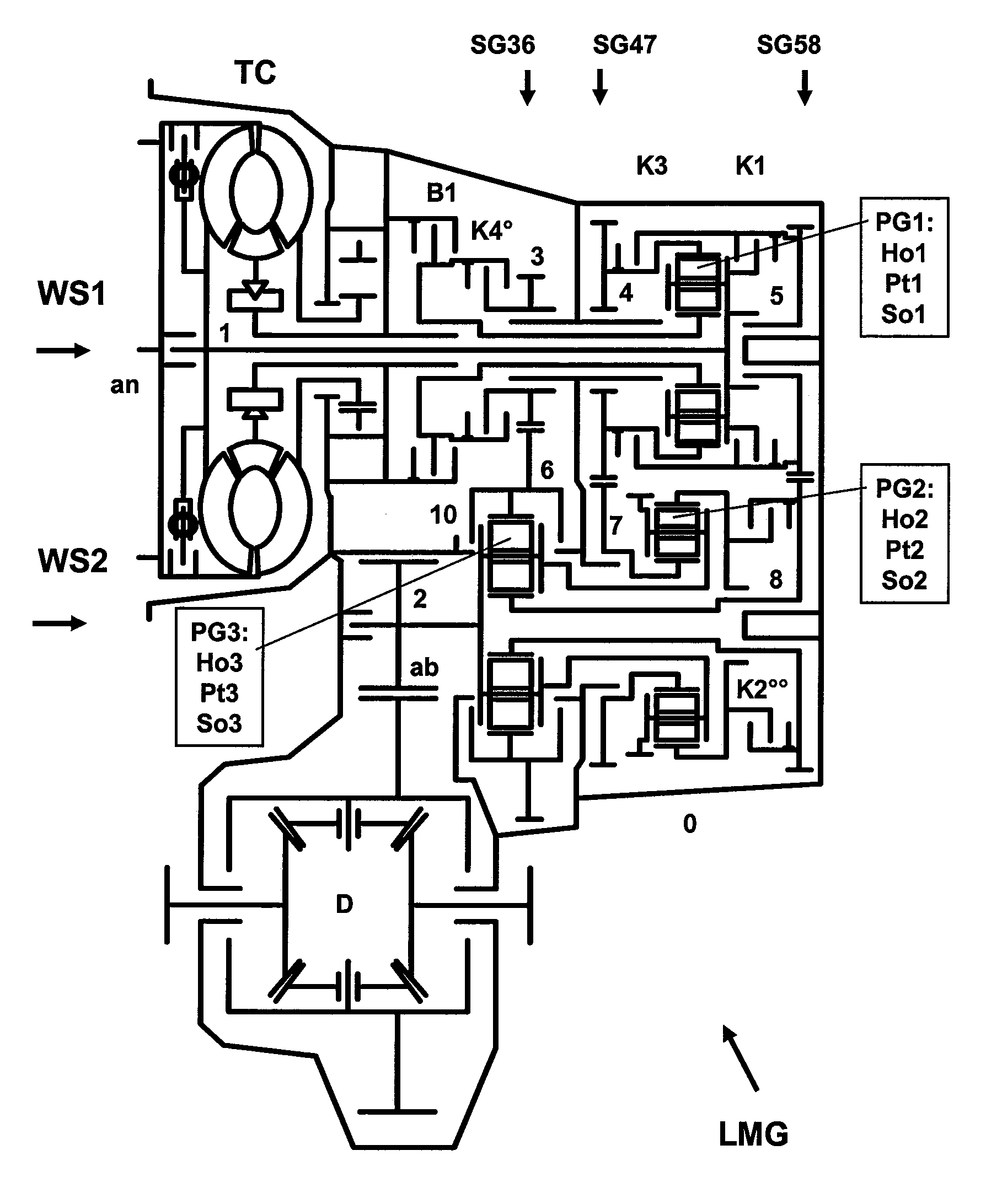
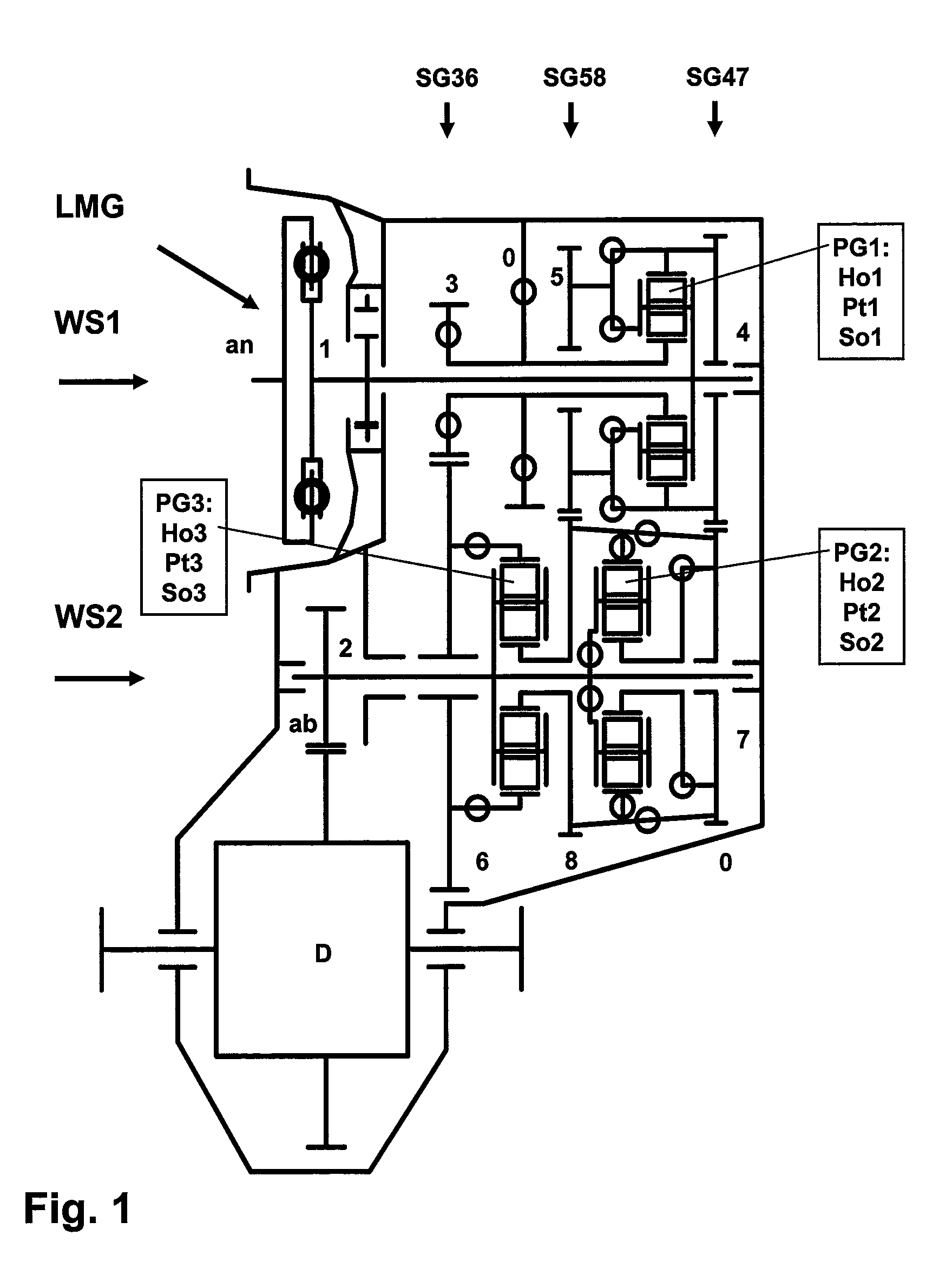
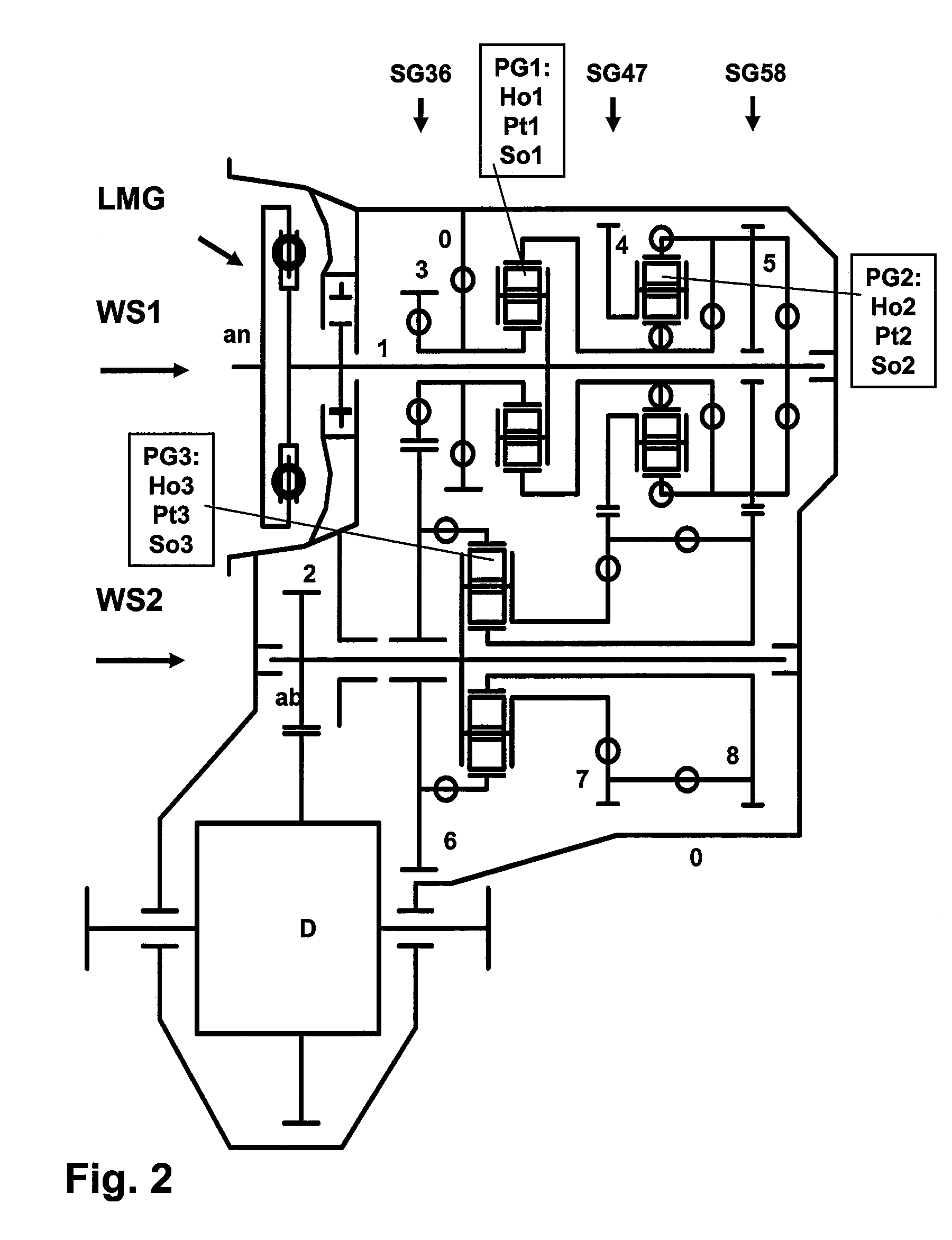
[0053]FIG. 1 shows a basic structure of the powershiftable multistage transmission LMG according to the invention. The input shaft an is connected through a torsional vibration damper to the first shaft 1 of the first shaft-line WS1. In parallel to this first shaft-line a second shaft-line WS2 is arranged. Among other elements this shaft-line WS2 contains the output shaft ab which is described as shaft 2. In a here shown front-cross application, the output shaft drives the differential D of the front axle via another gear set.

[0054]Besides the first shaft 1, the first shaft-line WS1 also comprises a third shaft 3, a fourth shaft 4 and a fifth shaft 5. Besides the second shaft 2, the second shaft-line WS2 also comprises a sixth shaft 6, a seventh shaft 7 and a eighth shaft 8.

[0055]Both shaft-lines WS1 and WS2 are connected through three transfer gears (SG36, SG47 and SG58). The first transfer gear SG36 connects the third shaft 3 with the sixth shaft 6. The second transfer gear SG47 c...


PUM


Abstract

A powershiftable multistage transmission (LMG) between an input shaft (an), which can be connected to a first transmission shaft (1), and an output shaft (ab=2) as a second transmission shaft, comprising two shaft-lines (WS1 and WS2) which are arranged in parallel in a transmission housing (0), three transfer gears (SG) between these shaft-lines, three planetary gears (PG) each with a sun gear (So), a ring gear (Ho) and a planet-carrier (Pt) with single planets, and a plurality, preferably five, shifting elements (SE). With only five shifting elements eight forward gears and one reverse gear can be switched. The six gear elements have ratios which can be designed easily even if the total ratio range is somewhere between 7<φges<9. Due to the distribution of the gear elements on two shaft-lines, the transmission gearbox has a short length and is suitable for front-cross-applications as well as inline-applications. All shifting elements can be easily fed with oil to control them. With only four shifting elements the transmission still has five well stepped forward gears and one reverse gear. The gear-trains 47 and 58 are very suitable gear elements to link to an electric motor to obtain an advantageous hybrid driveline.

Description

CROSS REFERENCE TO RELATED APPLICATIONS[0001]This application is a continuation of international patent application no. PCT / DE2008 / 000481, filed Mar. 19, 2008 designating the United States of America, and published in German on Oct. 2, 2008 as WO 2008 / 116449, the entire disclosure of which is incorporated herein by reference. Priority is claimed based on Federal Republic of Germany patent application no. DE 10 2007 014 150.7, filed Mar. 23, 2007.BACKGROUND OF THE INVENTION[0002]The invention relates to a powershiftable multistage transmission operating between an input shaft, which can be connected to a first shaft of the transmission, and an output shaft as a second shaft of the transmission, comprising two shaft-lines which are arranged in parallel in one transmission housing, three transfer gears, three planetary gears and several shifting elements, said first shaft-line having the first shaft as well as a third shaft, a fourth shaft and a fifth shaft and said second shaft-line h...

Claims


Application Information

Patent Timeline
Patent Type & Authority Patents(United States)
IPC IPC(8): F16H3/62
CPCF16H3/66F16H37/04F16H3/725B60K6/365B60K6/40B60K6/48Y02T10/6221F16H2200/006F16H2200/201F16H2200/2043Y02T10/62F16H3/62
Inventor TENBERGE, PETER
Owner EGS ENTWICKLUNGSGESELLSCHAFT FUR GETRIEBESYSTEME MBH
Why Eureka
Try Eureka