Apparatus and method for orienting an optical waveguide in relation to an optical unit of an optical module

Active Publication Date: 2005-10-06
AVAGO TECH INT SALES PTE LTD
View PDF6 Cites 2 Cited by
  • Summary
  • Abstract
  • Description
  • Claims
  • Application Information

AI Technical Summary

Benefits of technology

[0016] The solution according to one embodiment of the invention eliminates the alignment processes, as a result of which the cycle

Problems solved by technology

The problem generally arises of coupling an optical unit such as a vertically emitting laser or a photodiode to an optical waveguide in an e

Method used


Image

  • Apparatus and method for orienting an optical waveguide in relation to an optical unit of an optical module
  • Apparatus and method for orienting an optical waveguide in relation to an optical unit of an optical module
  • Apparatus and method for orienting an optical waveguide in relation to an optical unit of an optical module

Examples


Embodiment Construction

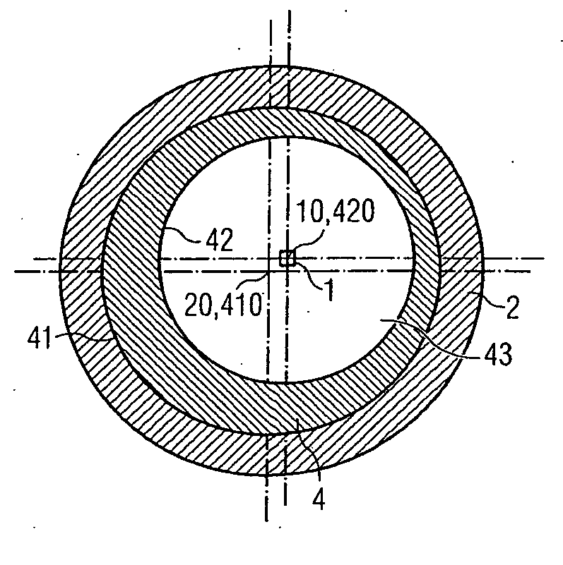
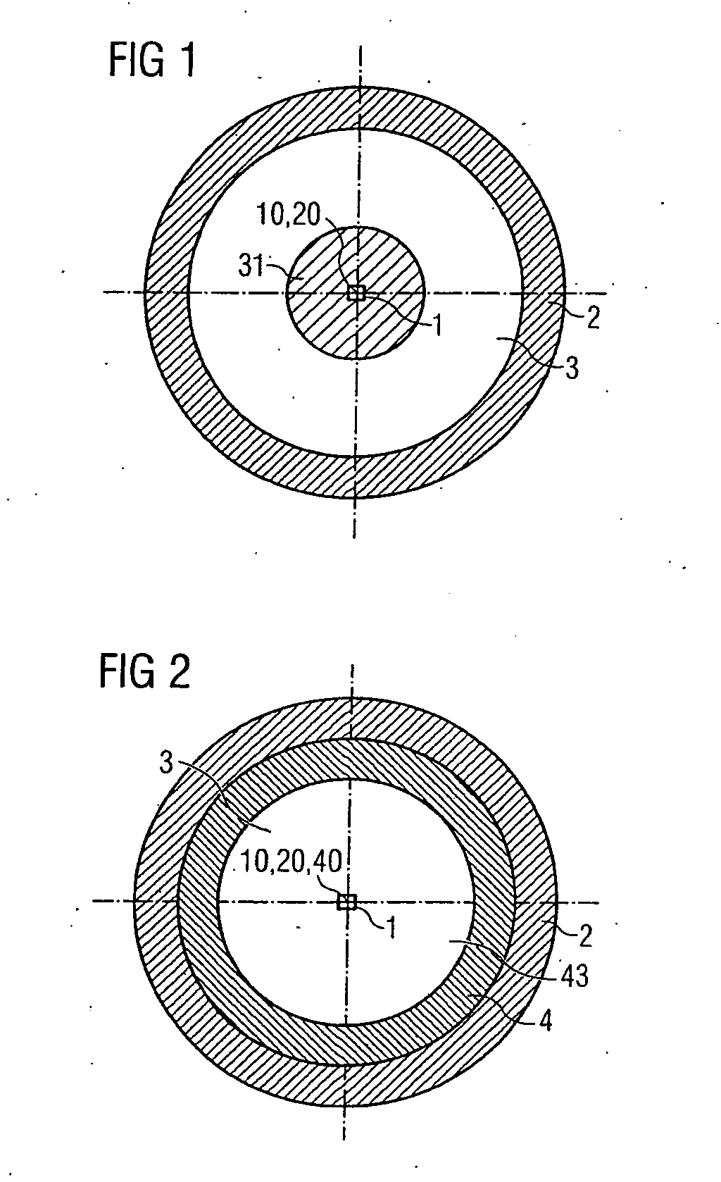
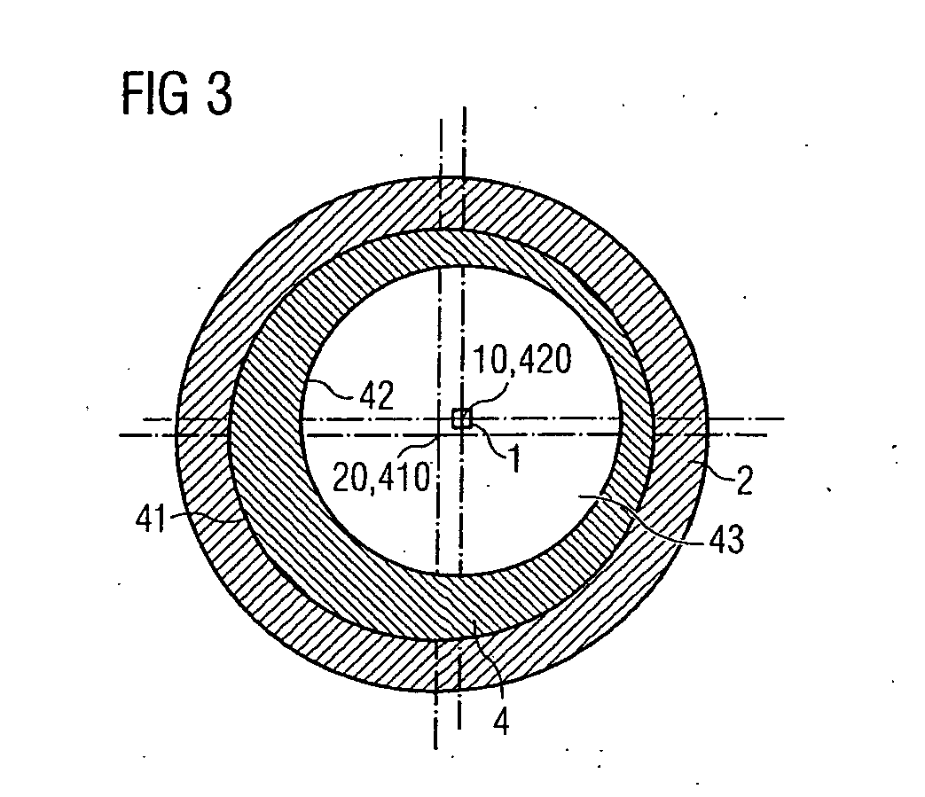
[0031] Firstly, the basic concept of the present invention is explained with reference to FIGS. 1 to 3. FIG. 1 shows a plan view of an optical unit 1 arranged on a reference area 3 of an optical module (not specifically illustrated). The optical module is in particular an optoelectronic transmitting module and / or an optoelectronic receiving module, for example an optoelectronic transceiver. The reference area 3 is for example the surface of a carrier substrate on which the optical unit 1 is mechanically fixed and electrically contact-connected in a manner known per se.

[0032] The optical unit 1 may be formed in any desired manner, in principle. A light emitting diode (LED), a vertically emitting laser diode (VCSEL), a photodiode, a mirror or some other optical functional area by means of which light is received or emitted is preferably involved. The optical unit is preferably formed as a prefabricated chip placed on the reference area 3. It is therefore also referred to as optical c...


PUM


Abstract

The invention relates to an apparatus and method for orienting an optical waveguide in relation to an optical unit arranged in or on an optical module. The optical module has a reference geometry which defines a first axis of symmetry. An offset between the optical axis of the optical unit and the axis of symmetry of the reference geometry is determined. A coupling element such as a sleeve is provided that serves to receive an optical waveguide that is to be oriented in relation to the optical unit. The sleeve has a hole defined by an internal contour thereof that defines a second axis of symmetry. The coupling element is arranged in relation to the optical module in such a way that the second axis of symmetry coincides with the optical axis of the optical unit.

Description

REFERENCE TO RELATED APPLICATION [0001] This application claims the benefit of the priority date of European patent application 04 090 085.4, filed on Mar. 4, 2004, the contents of which is herein incorporated by reference in its entirety. FIELD OF THE INVENTION [0002] The invention relates to an apparatus and method for orienting an optical waveguide in relation to an optical unit of an optical module. BACKGROUND OF THE INVENTION [0003] The problem generally arises of coupling an optical unit such as a vertically emitting laser or a photodiode to an optical waveguide in an effective manner. For this purpose, it is known to carry out an active alignment of the optical waveguide in relation to the optical unit. For this purpose, the optical waveguide is oriented to a maximum coupled-in or coupled-out power during operation of the optical unit and is fixed in this position. However, this active alignment process is very time- and cost-intensive and is accordingly not suitable for high...

Claims


Application Information

Patent Timeline
IPC IPC(8): G02B6/26G02B6/42
CPCG02B6/4221G02B6/4292G02B6/4226
Inventor HURT, HANS
Owner AVAGO TECH INT SALES PTE LTD
Why Eureka
Try Eureka