Method and apparatus for accurate calibration of a reflectometer by using a relative reflectance measurement

a technology of relative reflectance and calibration method, which is applied in the field of optical metrology, can solve the problems of difficult integration into systems suitable for use in semiconductor manufacturing environments, difficulty in detecting variations in calibration standards over time, and difficulty in fast and accurate calibration

Active Publication Date: 2010-02-16
BRUKER TECH LTD
View PDF92 Cites 3 Cited by
  • Summary
  • Abstract
  • Description
  • Claims
  • Application Information

AI Technical Summary

Benefits of technology

[0022]One embodiment of the current invention provides a means by which VUV reflectance data may be quickly and accurately calibrated. In one embodiment, the method enables simultaneous calibration of reflectance data covering a broad range of wavelengths. Additionally, the technique operates in a manner well suited for use in semiconductor manufacturing environments.
[0023]The method may be self-contained in that it may not require use of a second referencing instrument. It may provide a method by which calibration results may be autonomously verified such that use of third party certified standards will be reduced and / or altogether eliminated.
[0027]In another embodiment of the current invention a technique by which highly accurate thin film measurements may be performed is provided. The method may provide mathematical fitting algorithms with a more sensitive “goodness of fit” indicator that is less susceptible to noise present in the raw data. The fitting routine may be a spectrally driven fitting routine rather than relying solely on an amplitude driven routine (which typically incorporates difference calculations). In such an embodiment, the measurements may be obtained by utilizing the presence of sharp, narrow spectral features.
[0034]In another embodiment a method of calibrating a reflectometer which operates at wavelengths that include at least some wavelengths below deep ultra-violet (DUV) wavelengths is disclosed. The method may include providing a first calibration sample and a second calibration sample, wherein the reflectance properties of the first calibration sample and the second calibration sample are different. The method further includes collecting a first set of data from a first calibration sample, the first set of data including at least some intensity data collected for wavelengths below DUV wavelengths. The method also includes collecting a second set of data from the second calibration sample, the second set of data including at least some intensity data collected for wavelengths below DUV wavelengths. Further, the method may include utilizing a ratio based on the first set of data and the second set of data to determine a reflectance of at least one of the first calibration sample and the second calibration sample to assist in calibrating the reflectometer at wavelengths that include at least some DUV wavelengths.

Problems solved by technology

The push towards thinner layers and the introduction of complicated new materials have challenged the sensitivity of such instrumentation.
Due to the complexity of absolute reflectometer systems, commercial reflectometers generally measure reflected intensity, which is calibrated to a known absolute reflectance standard.
In fact, variations in the calibration standard over time are generally not detectable using the above method, since such changes are simply “calibrated out”.
Some calibration techniques involve complicated optical arrangements that incorporate moving mirrors.
While such methods offer a means of obtaining calibrated reflectance data, they generally suffer from the fact that they are time-consuming, involve considerable mechanical motion and can not easily be integrated into systems suitable for use in semiconductor manufacturing environments.
Integration of a separate reference ellipsometer into an optical measurement system in order to calibrate the first optical measurement device is both complicated and expensive.
Additionally, it would be advantageous if this method specifically enabled the accurate calibration of reflectometry data at wavelengths encompassing the VUV spectral region, where small uncertainties in the properties of third party certified standards can result in substantial errors.
Unfortunately, there are limits to the measurement accuracy that can be attained using conventional “goodness of fit” parameters.

Method used


Image

  • Method and apparatus for accurate calibration of a reflectometer by using a relative reflectance measurement
  • Method and apparatus for accurate calibration of a reflectometer by using a relative reflectance measurement
  • Method and apparatus for accurate calibration of a reflectometer by using a relative reflectance measurement

Examples


Embodiment Construction

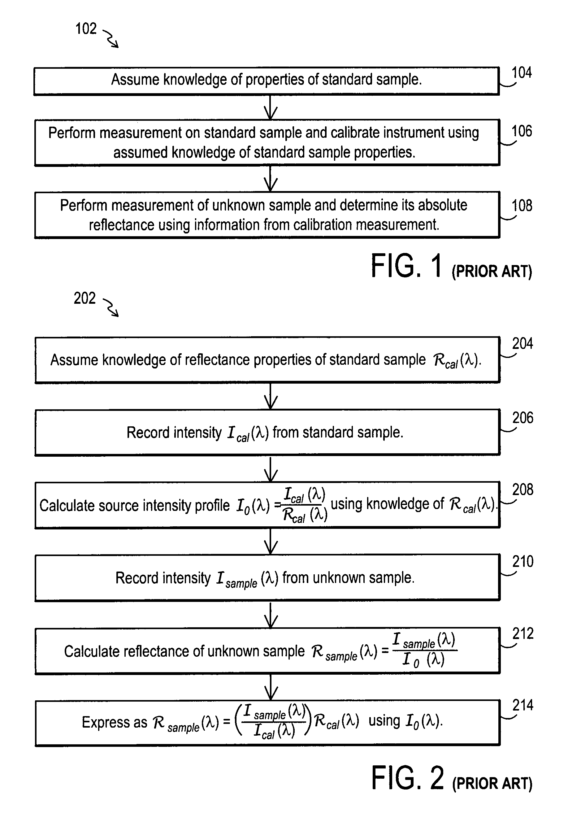
[0067]The manner in which standard samples are typically used to calibrate reflectometers is generally presented in the flowchart 102 of FIG. 1. As is evident in the figure the first step 104 in the calibration process is to assume knowledge of the reflectance properties of the standard sample. With this information in hand, the intensity of light reflected from the sample as a function of wavelength can be recorded and the reflectometer calibrated in step 106. Subsequently, the reflectance of unknown samples may then be absolutely determined with the device in step 108.

[0068]A more detailed description of this calibration procedure is outlined in the flowchart 202 of FIG. 2 wherein the mathematical relationships involved in calculating the absolute reflectance of an unknown sample are presented. FIG. 2 illustrates the flowchart 202 for the calibration procedure. In a first step 204, knowledge of reflectance properties of a standard sample is assumed. Then in step 206 the intensity ...


PUM


Abstract

A reflectometer calibration technique is provided that may include the use of two calibration samples in the calibration process. Further, the technique allows for calibration even in the presence of variations between the actual and assumed properties of at least one or more of the calibration samples. In addition, the technique utilizes a ratio of the measurements from the first and second calibration samples to determine the actual properties of at least one of the calibration samples. The ratio may be a ratio of the intensity reflected from the first and second calibration samples. The samples may exhibit relatively different reflective properties at the desired wavelengths. In such a technique the reflectance data of each sample may then be considered relatively decoupled from the other and actual properties of one or more of the calibration samples may be calculated. The determined actual properties may then be utilized to assist calibration of the reflectometer.

Description

CROSS-REFERENCE TO RELATED APPLICATIONS[0001]This application is a continuation-in-part application of U.S. patent application Ser. Nos. 11 / 418,827 filed May 5, 2006 now U.S. Pat. No. 7,282,703 and 11 / 418,846 filed May 5, 2006, both of which are continuation-in-part applications of U.S. patent application Ser. No. 10 / 930,339 filed Aug. 31, 2004 which claims priority to Provisional Patent Application No. 60 / 600,599 filed Aug. 11, 2004; the disclosures of which are each expressly incorporated herein by reference.BACKGROUND OF THE INVENTION[0002]The present invention relates to the field of optical metrology. More specifically, it provides a method by which reflectance data may be accurately calibrated. In one embodiment it provides a method by which broad-band vacuum ultraviolet (VUV) reflectance data may be accurately calibrated. Additionally, it also provides a method by which highly accurate thin film measurements may be performed.[0003]Optical reflectometry techniques have long be...

Claims


Application Information

Patent Timeline
Patent Type & Authority Patents(United States)
IPC IPC(8): G12B13/00
CPCG01B11/0625G01N21/276G01N21/278G01N21/9501G01N21/211G01N21/33
Inventor WALSH, PHILLIPHARRISON, DALE A.
Owner BRUKER TECH LTD
Why Eureka
Try Eureka