Printing apparatus and printing control method

Active Publication Date: 2010-09-23
CANON KK
View PDF9 Cites 7 Cited by
  • Summary
  • Abstract
  • Description
  • Claims
  • Application Information

AI Technical Summary

Benefits of technology

[0015]According to the above-described configuration, the temperature sensor for the print head can be quickly and accurately

Problems solved by technology

As a result, a density distribution may occur in the printed image, thus degrading print quality.
However, directly sensing the ink temperature is difficult.
Thus, maintaining

Method used


Image

  • Printing apparatus and printing control method
  • Printing apparatus and printing control method
  • Printing apparatus and printing control method

Examples


Example

[0026]An embodiment of the present invention will be described below in detail with reference to the drawings.

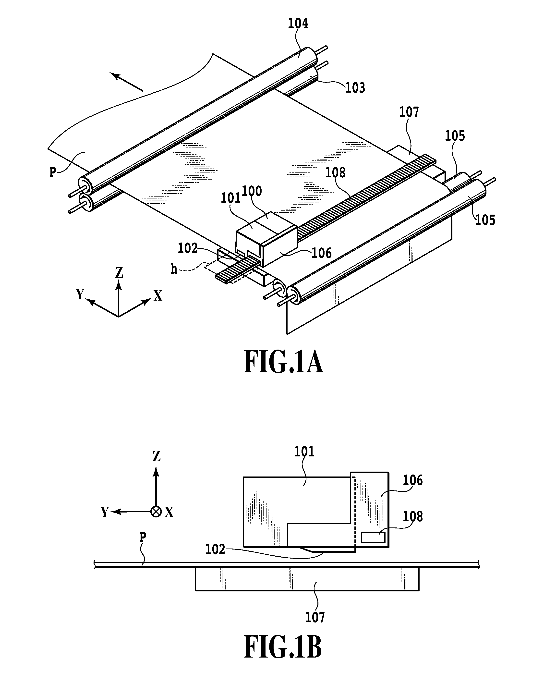
[0027]FIGS. 1A and 1B are diagrams schematically showing a printing apparatus according to the present embodiment. FIG. 1A is a perspective view showing an ink jet printing apparatus. FIG. 1B is a sectional view showing a Y-Z cross section of a print head 101.

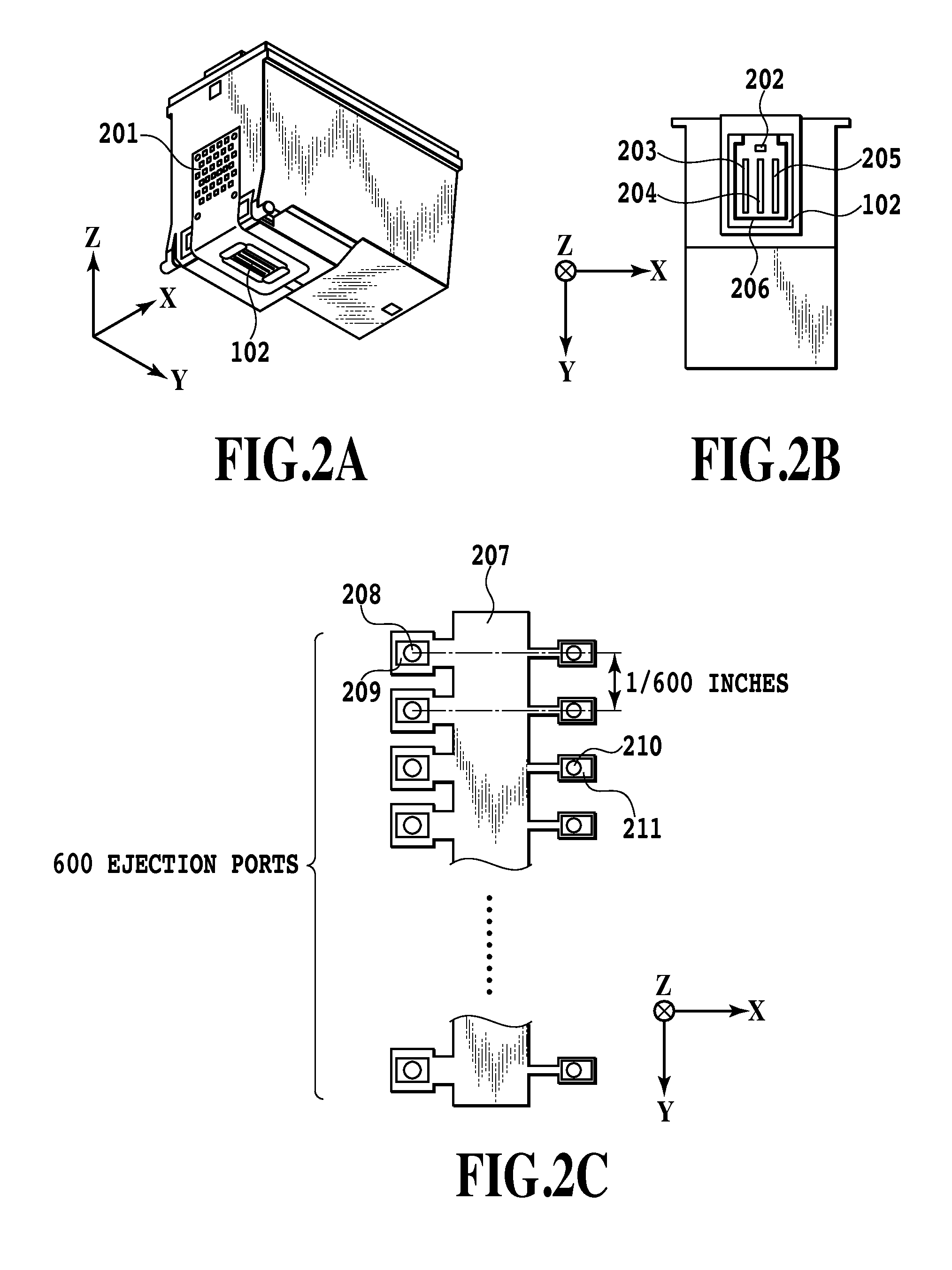
[0028]A print head 100 is integrated with an ink tank configured to accommodate black ink, light cyan ink, and light magenta ink. The print head 101 is integrated with an ink tank configured to accommodate cyan ink, magenta ink, and yellow ink. Each of the print heads 100 and 101 includes a plurality of ejection ports 102 arranged in association with each of the ink.

[0029]A conveying roller 103 and an auxiliary roller 104 rotate in the directions of arrows in FIG. 1A while cooperating in pressing a print medium P, thus conveying the print medium P in a sub-scanning direction (Y direction in FIG. 1A) as required. A sheet...


PUM


Abstract

The present invention uses a temperature sensor to sense the temperature of a print head configured to eject ink, and senses the environmental temperature of a printing apparatus. The temperature of the print head is corrected based on the environmental temperature only if information from the temperature sensor is different from the last information acquired.

Description

BACKGROUND OF THE INVENTION[0001]1. Field of the Invention[0002]The present invention relates to a printing apparatus and printing control method, and in particular, to a printing apparatus including temperature sensing means for a print head, and a printing control method.[0003]2. Description of the Related Art[0004]A thermal ink jet printing method (hereinafter also referred to as an ink jet printing method) performs printing by energizing heaters to generate heat energy, thus generating bubbles in ink. In an inkjet printing apparatus, ink ejection amount (the volume of ink pushed out through nozzles) and ink ejection speed are significantly affected by the temperature of the ink (hereinafter also referred to as the ink temperature) near the heaters. An increase in ink temperature increases the ink ejection amount and the ink ejection speed. On the other hand, a decrease in ink temperature reduces the ink ejection amount and the ink ejection speed.[0005]A change in ink ejection am...

Claims


Application Information

Patent Timeline
IPC IPC(8): B41J29/38
CPCB41J2/0454B41J2/0458B41J2/04563
Inventor TANAKA, HIROKAZUKANDA, HIDEHIKOHIROSAWA, SUSUMUYAMAMOTO, WAKAKOOONUKI, KENICHI
Owner CANON KK
Why Eureka
Try Eureka