
System and method to calibrate multiple sensors

a technology of sensors and sensors, applied in the field of inspection sensors, can solve the problems of adversely increasing the manufacturing cost of composite structures, affecting the efficiency of inspection sensors, and single-mode targets designed to work for one optical sensor, and achieves the effects of improving overall system efficiency, saving time, and ensuring accuracy

Active Publication Date: 2010-03-23
LOCKHEED MARTIN CORP
View PDF6 Cites 8 Cited by
  • Summary
  • Abstract
  • Description
  • Claims
  • Application Information

AI Technical Summary

Benefits of technology

The present invention provides a system and method to calibrate a laser ultrasound system using a multi-mode calibration target. This target provides both depth and visual contrast in a single target, allowing for a common focal point for the optical components of the system. The multi-mode target can be used to calibrate multiple sensors prior to using the laser ultrasound equipment, reducing errors and improving efficiency. The multi-mode target can be easily positioned and removed from the inspection field, and can provide a common focal point for the optical components of the system. The use of a multi-mode calibration target eliminates the need for unique calibration targets for each optical component, saving time and improving accuracy.

Problems solved by technology

Conventional NDE methods are slow, labor-intensive, and costly.
As a result, testing procedures adversely increase the manufacturing costs associated with composite structures.
A single-mode target, designed to work for one optical sensor, will not function properly as a target for a different optical system operating at a different wavelength.
For example, a flat target having a contrasting pattern can serve as a suitable target for an optical camera, but will not serve as a suitable target for a depth camera.
Calibrating each optical sensor independently with a single-mode target is labor intensive, time consuming and can introduce intersection errors in the calibration process.
Errors introduced in the calibration process will result in imprecise measurements when the laser ultrasound system is operating in the final world framework.

Method used


Image

  • System and method to calibrate multiple sensors
  • System and method to calibrate multiple sensors
  • System and method to calibrate multiple sensors

Examples


Embodiment Construction

[0026]Preferred embodiments of the present invention are illustrated in the FIGs., like numerals being used to refer to like and corresponding parts of the various drawings.

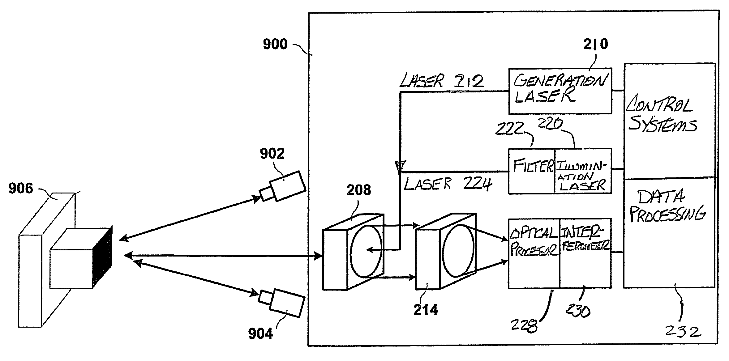
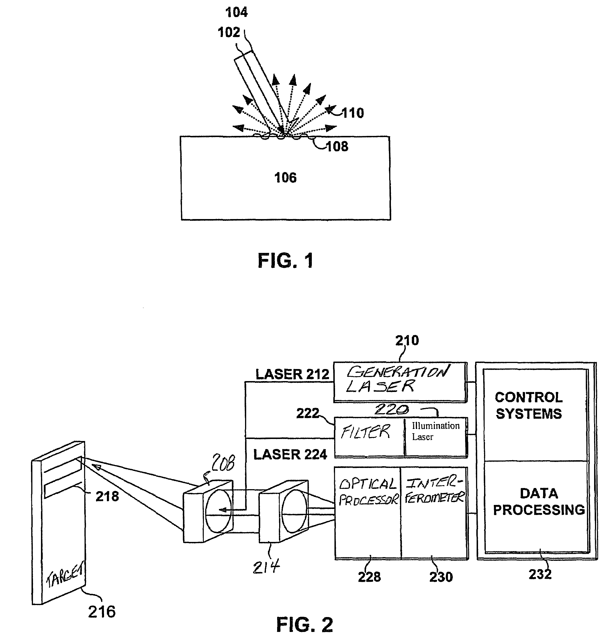
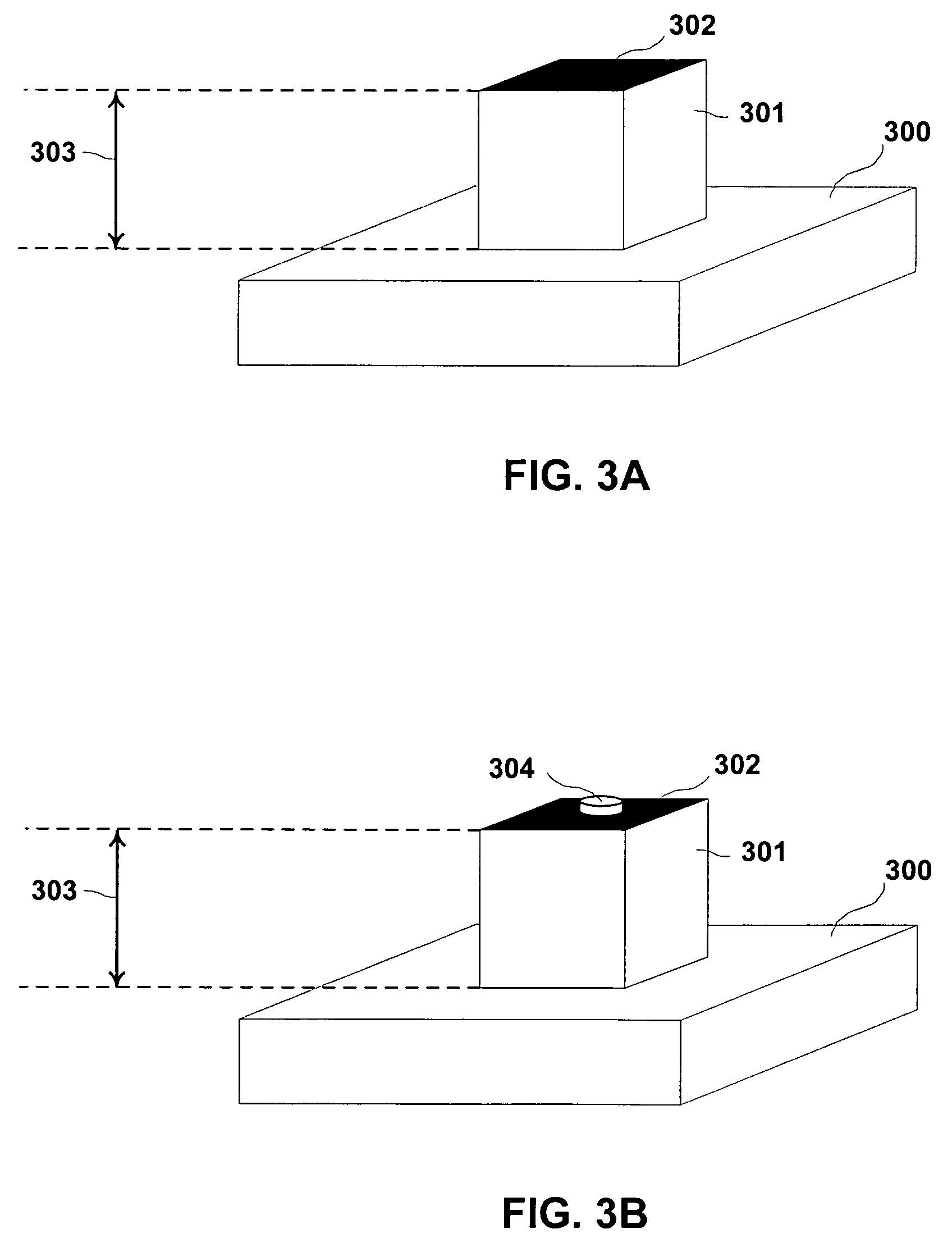
[0027]The present invention provides the ability to use the single multi-mode calibration target to calibrate multiple sensor devices. This multi-mode calibration target may be viewed by sensors such as optical cameras and depth cameras. The multi-mode calibration target may also be used to calibrate ultrasonic sensors. Contrasting colors allow cameras sensitive to visible light to see the target. Additionally, the target may also include depth discontinuities on the surfaces. To calibrate the ultrasonic sensors other discontinuities may be included within the target. For example, discontinuities in density, texture, composition may be used. By having contrasting colors and depth discontinuities on the same target, different visualization or ultrasonic devices may be calibrated or aligned based on the exact same ...


PUM

PropertyMeasurementUnit
wavelengthaaaaaaaaaa
poweraaaaaaaaaa
ultrasonic surface displacementsaaaaaaaaaa

Abstract

The present invention provides a multi-mode calibration target operable to calibrate multiple optical sensors. One embodiment has multiple planar surfaces, wherein the multiple planar surfaces are able to be distinguished by visual sensors based on their color, hue, shade, tint, or tone. Additionally, these planar surfaces may be raised or recessed from one another to provide depth contrast as well as visual contrast. Other embodiments may include narrow band emitters such as laser diodes located at predetermined locations within the multi-mode target. These targets may then be used to calibrate various sensors, such as optical sensors, within an inspection system such as a laser ultrasonic inspection system.

Description

TECHNICAL FIELD OF THE INVENTION[0001]The present invention relates generally to the calibration of inspection sensors, and more particularly, to a system and method for calibrating multiple sensors using a multi-mode target system.BACKGROUND OF THE INVENTION[0002]In recent years, the use of advanced composite structures has experienced tremendous growth in the aerospace, automotive, and many other commercial industries. While composite materials offer significant improvements in performance, they require strict quality control procedures in both the manufacturing processes and after the materials are in service in finished products. Specifically, non-destructive evaluation (NDE) methods must assess the structural integrity of composite materials. This assessment detects inclusions, delaminations and porosities. Conventional NDE methods are slow, labor-intensive, and costly. As a result, testing procedures adversely increase the manufacturing costs associated with composite structur...

Claims


Application Information

Patent Timeline
Patent Type & Authority Patents(United States)
IPC IPC(8): G01N29/04
CPCG01N21/1717G01N21/45G01N29/2418G01N29/30G01N2021/8472G01N2291/0231
Inventor TURNER, WESLEY DAVIDNAFIS, CHRISTOPHER ALLEN
Owner LOCKHEED MARTIN CORP
Learn More