Method of calibrating ultrasound velocity

a technology of ultrasound velocity and calibration method, which is applied in the direction of instruments, ultrasonic/sonic/infrasonic diagnostics, structural/machine measurement, etc., can solve the problems of inaccurate calibration of velocity, affecting the application in clinical diagnosis, and long operation time, so as to improve accuracy, improve velocity, and reduce operation time

Active Publication Date: 2015-04-16
NAT TAIWAN UNIV
View PDF7 Cites 0 Cited by
  • Summary
  • Abstract
  • Description
  • Claims
  • Application Information

AI Technical Summary

Benefits of technology

[0013]According to embodiments of the present invention, the method calibrates better velocity among various velocities in a parallel way; therefore, the operation time is decreased and the accuracy is improved so that ultrasound imaging with the calibrated velocity according to embodiments of the present invention has better images. Thus, the diagnosis is more accurate and more effective.

Problems solved by technology

In prior art, methods of calibrating ultrasound velocity have problems of longer operation time and inaccurate calibration of velocity, which further affects the application in clinical diagnosis.

Method used


Image

  • Method of calibrating ultrasound velocity
  • Method of calibrating ultrasound velocity
  • Method of calibrating ultrasound velocity

Examples


Embodiment Construction

[0021]The present invention relates to a method of calibrating ultrasound velocity. In the following description, numerous details are set forth in order to provide a thorough understanding of the present invention. It will be appreciated by one skilled in the art that variations of these specific details are possible while still achieving the results of the present invention. In other instance, well-known components are not described in detail in order not to unnecessarily obscure the present invention.

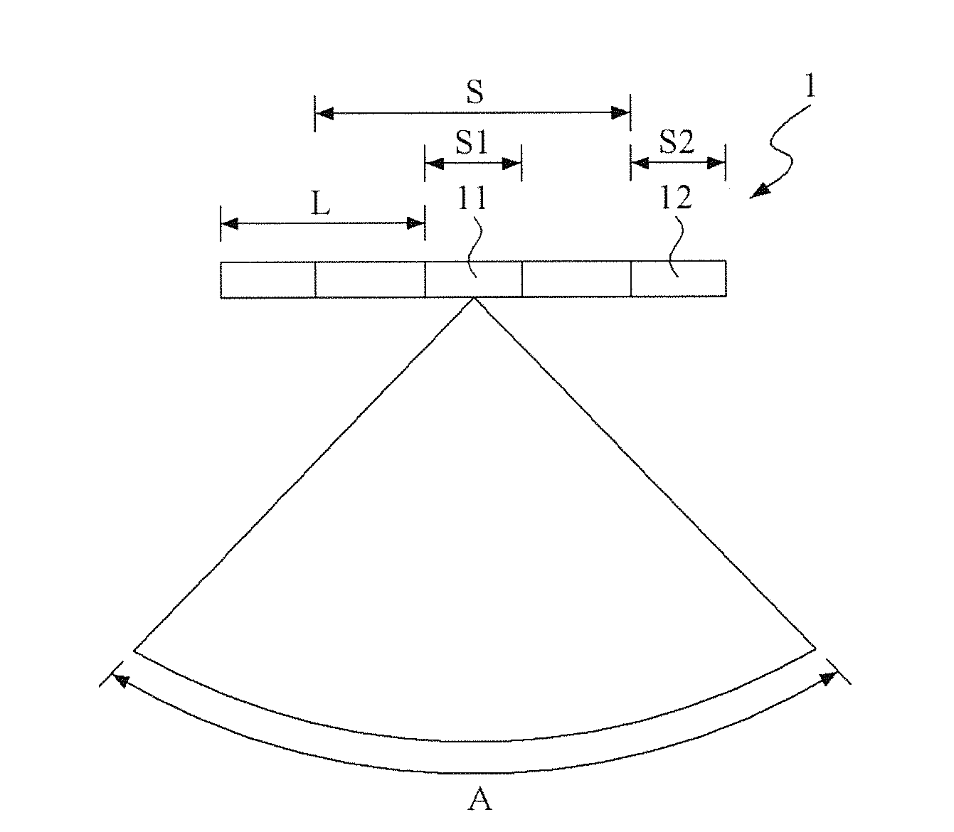
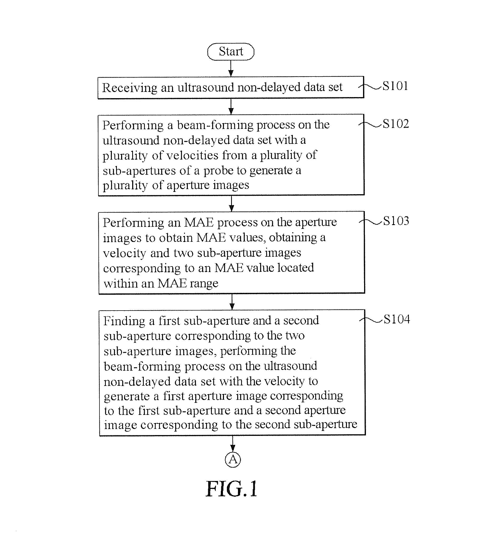
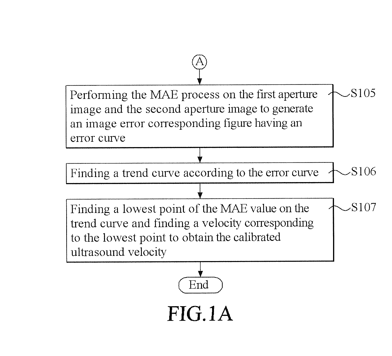
[0022]Refer to FIG. 1 to FIG. 4. FIG. 1 and FIG. 1A are flow charts showing a method of calibrating ultrasound velocity according to a preferable embodiment of the present invention. FIG. 2 is a schematic view showing a probe of the preferable embodiment of the present invention. FIG. 3 is a schematic view showing a relation among MAE values, distances between a first and a second sub-aperture, and sizes of the second sub-aperture according to the preferable embodiment of the present...


PUM

PropertyMeasurementUnit
mean velocityaaaaaaaaaa
velocityaaaaaaaaaa
velocityaaaaaaaaaa

Abstract

A method of calibrating ultrasound velocity is provided, including receiving an ultrasound non-delayed data set; performing a beam-forming process on the ultrasound non-delayed data set with a plurality of velocities to generate a plurality of aperture images; performing an MAE (Mean Absolute Error) process to obtain a velocity and two sub-aperture images corresponding to an MAE value located within an MAE range; finding a first sub-aperture and a second sub-aperture corresponding to the two sub-aperture images, generating a first aperture image and a second aperture image with corresponding velocity; performing the MAE process on the first aperture image and the second aperture image to generate an image error corresponding figure having an error curve; finding a trend curve according to the error curve; and finding a lowest point of MAE value on the trend curve and finding a velocity correspondingly to obtain the calibrated ultrasound velocity.

Description

[0001]This application claims the benefits of the Taiwan Patent Application Serial NO. 102136744 filed on Oct. 11, 2013, the subject matter of which is incorporated herein by reference.BACKGROUND OF THE INVENTION[0002]1. Field of the Invention[0003]The present invention relates to a method of calibrating ultrasound velocity and more particularly, relates to a method of calibrating ultrasound velocity by finding locations of two sub-apertures and performing an MAE process on two sub-aperture images to obtain calibrated ultrasound velocity.[0004]2. Description[0005]The technique of generating images by means of ultrasound has been widely adopted in biomedical applications. Compared with other medical imaging systems such as X-ray, computed tomography (CT), magnetic resonance imaging (MRI) and nuclear medicine imaging utilized in clinic, ultrasonic imaging has advantages of cost effectiveness, non-invasiveness, no ionizing radiation, real-time imaging capability, high spatial resolutio...

Claims


Application Information

Patent Timeline
Patent Type & Authority Applications(United States)
IPC IPC(8): G01N29/30G01N29/24
CPCG01N29/30G01N29/24A61B8/5269A61B8/58G01N29/262G01N29/4454
Inventor LI, PAI-CHIWEI, YU-MING
Owner NAT TAIWAN UNIV
Why Eureka
Try Eureka