
Lock device of sliding mechanism

a technology of sliding mechanism and lock device, which is applied in the direction of belt retraction device, vehicle safety belt, belt anchoring device, etc., can solve the problem that the runner (moving member) cannot be locked at an interval smaller than the distan

Inactive Publication Date: 2010-03-09
HONDA MOTOR CO LTD
View PDF4 Cites 9 Cited by
  • Summary
  • Abstract
  • Description
  • Claims
  • Application Information

AI Technical Summary

Benefits of technology

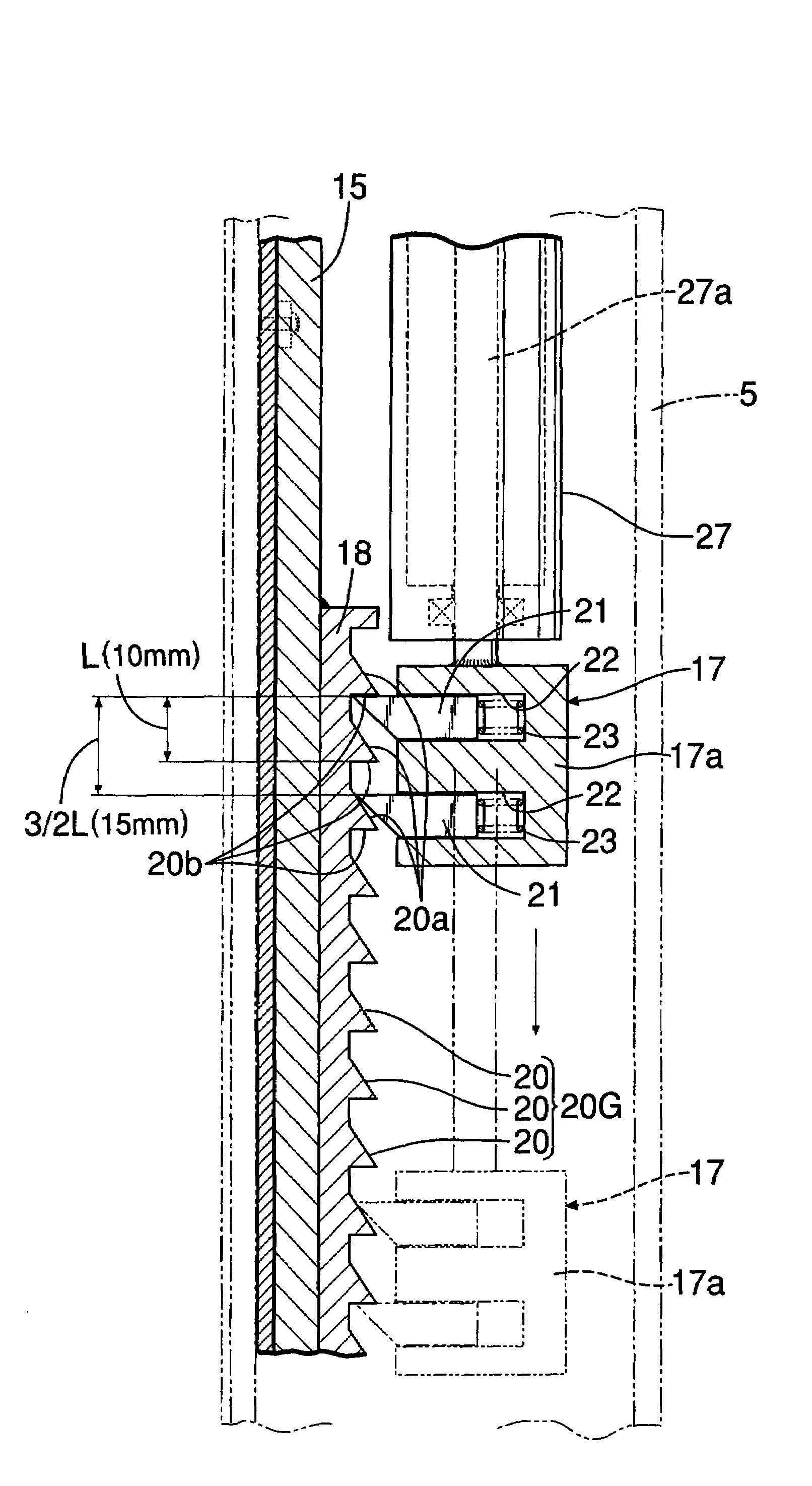
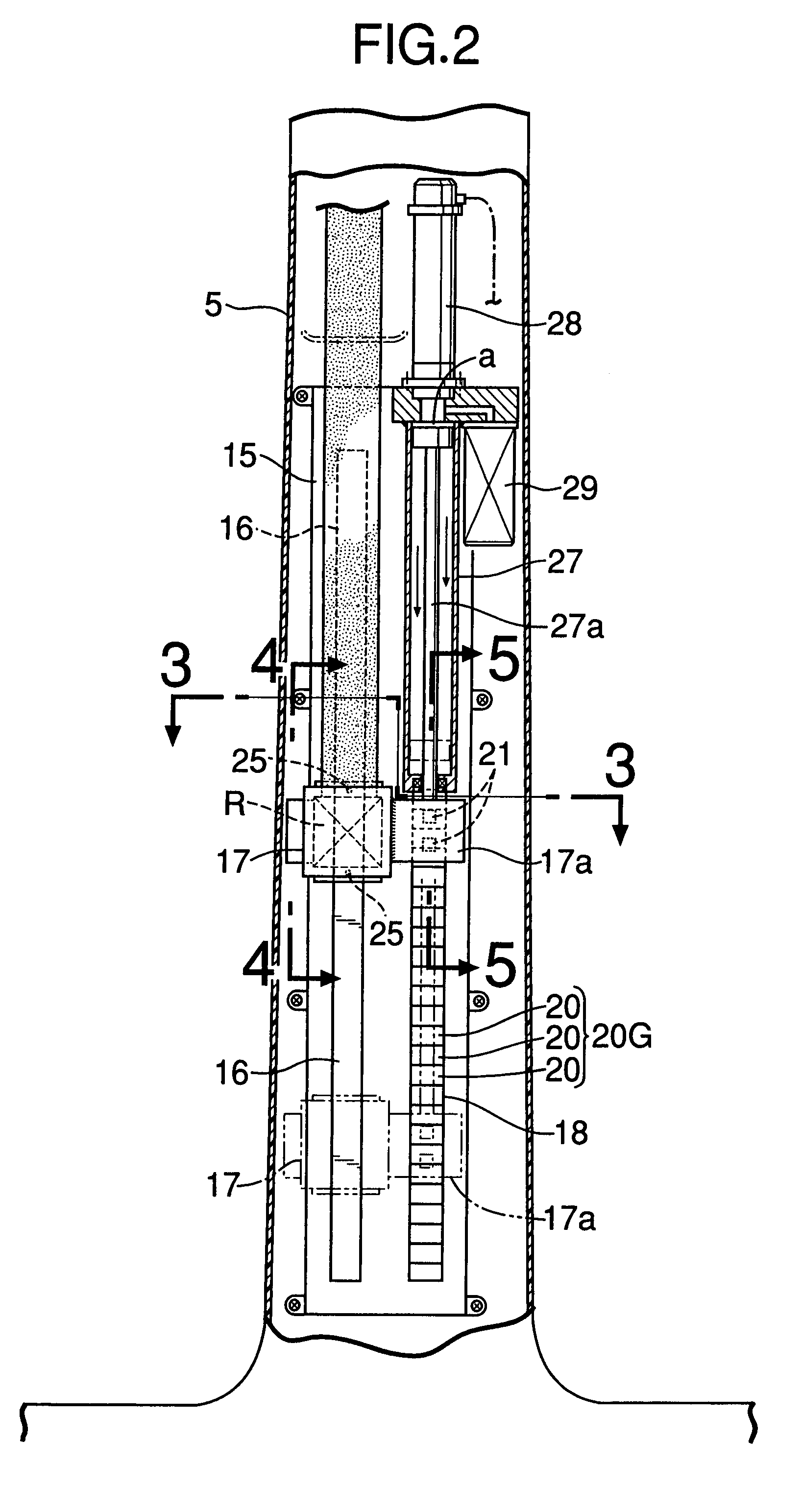
The present invention provides a lock device for a sliding mechanism that allows a moving member to be locked at a smaller interval in sliding in the opposite direction than conventional lock devices. This is achieved by using a guide rail, a moving member, at least a pair of locking members, and a group of locking grooves arranged in a sliding direction of the moving member. The locking members selectively engage with different ones of the locking grooves to lock the moving member in various engagement positions. The distance between the locking members is longer than the distance between adjacent ones of the locking grooves, allowing the moving member to become locked in one of the engagement positions on the guide rail after moving an interval smaller than the distance between the locking grooves in the opposite direction. The invention also allows for the locking of a retractor slidably mounted in a seat belt of a vehicle at a smaller interval than previously possible.

Problems solved by technology

Therefore, a locking interval of the runner (moving member) is restricted by the distance between the locking holes, leading to a problem that the runner (moving member) cannot be locked at an interval smaller than the distance between the locking holes.

Method used


Image

  • Lock device of sliding mechanism
  • Lock device of sliding mechanism
  • Lock device of sliding mechanism

Examples


first embodiment

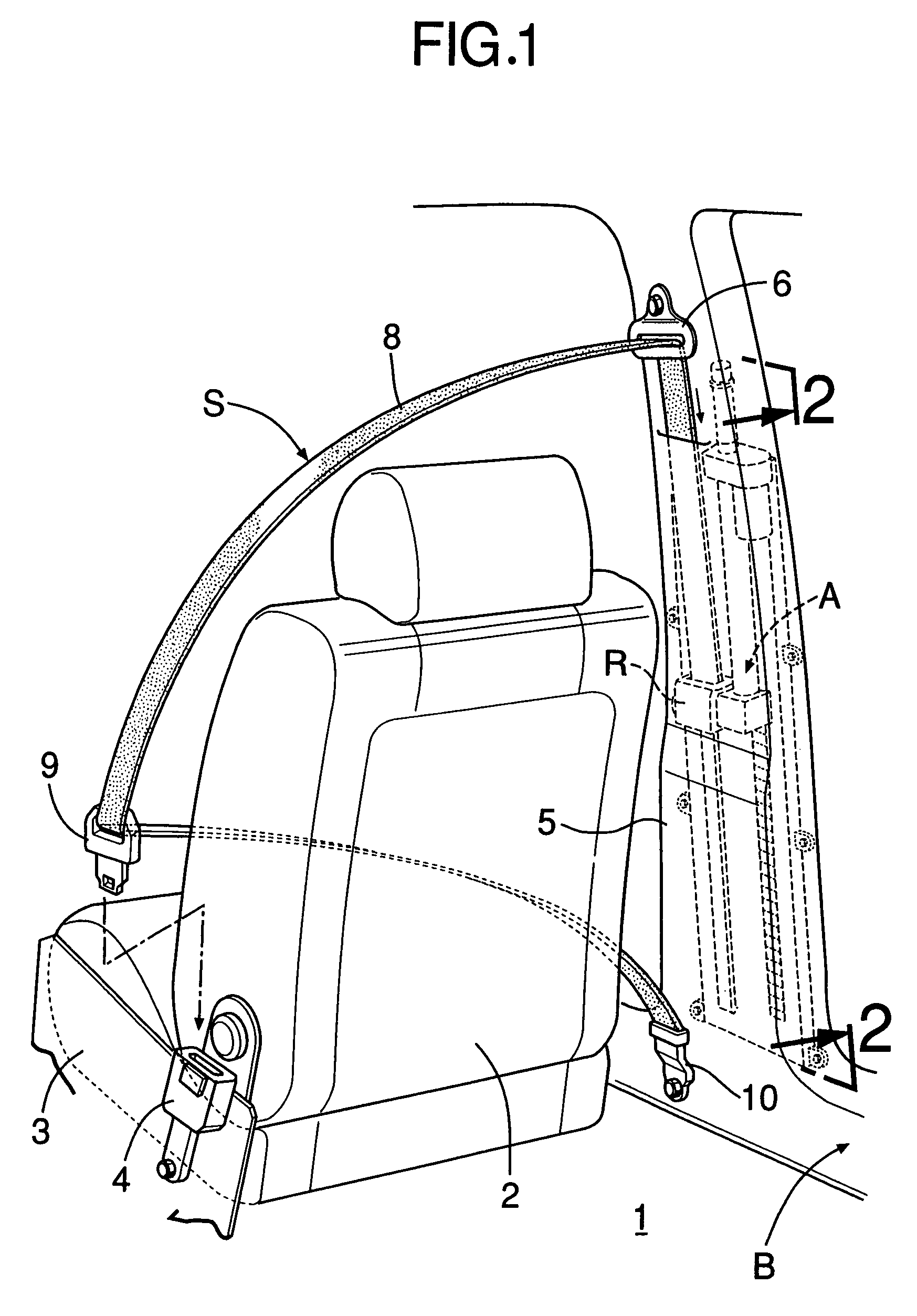
[0023]the present invention will be described with reference to FIGS. 1 to 5.

[0024]Referring to FIG. 1, a seat 2 is provided on a floor panel 1 constituting a portion of a vehicle body B, and is equipped with a seat belt device S.

[0025]At a lower portion on one side of the seat 2, a buckle 4 is mounted on a support frame 3 above the floor panel 1. A shoulder through-anchor 6 is mounted at an upper portion of a center pillar 5. A buckle plate 9 is slidably mounted on the seat belt 8 so that it can disengageably engage with the buckle 4. The seat belt 8 is slidably carried in the shoulder through-anchor 6. Below the shoulder through-anchor 6, a retractor R is supported on the center pillar 5 so that it can vertically slide as described later. The seat belt 8 is attached at its one end to the retractor R and wound into the retractor R so that it can be drawn out of the retractor R. The seat belt 8 drawn out of the retractor R is passed through the shoulder through-anchor 6 and the buck...


PUM


Abstract

In a lock device of a sliding mechanism, a pair of locking claws provided on a moving member are brought into resilient engagement with locking grooves of a locking groove group, whereby downward sliding of the moving member is permitted but upward sliding thereof is locked. The distance between the locking claws is longer than distance between the locking grooves, so that the moving member becomes locked against upward sliding at an interval smaller than the distance between the locking grooves. Thus, the moving member adapted to slide in one (downward) direction along a guide rail can be reliably locked against movement in the opposite (upward) direction at a very small interval.

Description

CROSS-REFERENCE TO RELATED APPLICATIONS[0001]The present invention claims priority under 35 USC 119 based on Japanese patent application No. 2006-69414, filed on Mar. 14, 2006. The subject matter of this priority document is incorporated by reference herein.BACKGROUND OF THE INVENTION[0002]1. Field of the Invention[0003]The present invention relates to a lock device of a sliding mechanism, in which in order to provide a unidirectional moving property to a moving member adapted to slide in one direction along a guide rail, sliding of the moving member in the opposite direction can be locked at a very small interval.[0004]2. Description of the Related Art[0005]Japanese Patent Application Laid-open No. 2001-113995 discloses a lock device of a sliding mechanism, in which a moving member is adapted to slide along a fixed guide rail and may be locked in numerous positions on the guide rail.[0006]In the lock device disclosed in Japanese Patent Application Laid-open No. 2001-113995, a serie...

Claims


Application Information

Patent Timeline
Patent Type & Authority Patents(United States)
IPC IPC(8): B60R22/46B60R22/195
CPCB60R22/1951B60R22/1955B60R22/24
Inventor FUJII, DAISUKEMORI, MIKIMOTOZAWA, YASUKI
Owner HONDA MOTOR CO LTD
Learn More