Hopper fed tee-nut having counterbore with nylon lock

Active Publication Date: 2010-03-09
STAFAST PROD
View PDF138 Cites 26 Cited by
  • Summary
  • Abstract
  • Description
  • Claims
  • Application Information

AI Technical Summary

Benefits of technology

[0008]The tee nut comprises a flange which includes an upper portion and a lower portion. The upper and lower portions of the tee nut slide within the guides. The tee nut includes a shank or barrel extending perpendicularly from the upper portion of the flange and a head extending perpendicularly from the lower portion of the flange. The flange includes four elongated teeth which extend perpendicularly from the flange and which are inserted deeply into a wooden substrate. A passageway extends through the barrel, flange and head. The passageway includes a stepped bore, a cavity, and female threads within the bore for interengagement with a stud. The passageway includes a first-counterbored entranceway for reception of a threaded stud. The first counterbore accommodates misalignment of the threaded stud with respect to the entranceway to the passageway so as to guide the threaded stud into the female threaded portion of the passageway. A locking ring resides in the cavity in the passageway.
[0015]It is a further object of the instant invention to provide a tee-nut which includes prongs or teeth which extend from a flange in combination with a nylon locking ring positioned such that the tee-nut will not be forcefully separated from a substrate in which it is embedded.

Problems solved by technology

However, since the nylon locking ring is not very thick or deep the prongs or teeth of the tee nut cannot escape (longitudinally, i.e., in the direction of travel of the bolt) from the substrate thus enabling the bolt to be completely threaded into the tee-nut resulting in a secure fastening device.

Method used


Image

  • Hopper fed tee-nut having counterbore with nylon lock
  • Hopper fed tee-nut having counterbore with nylon lock
  • Hopper fed tee-nut having counterbore with nylon lock

Examples


Embodiment Construction

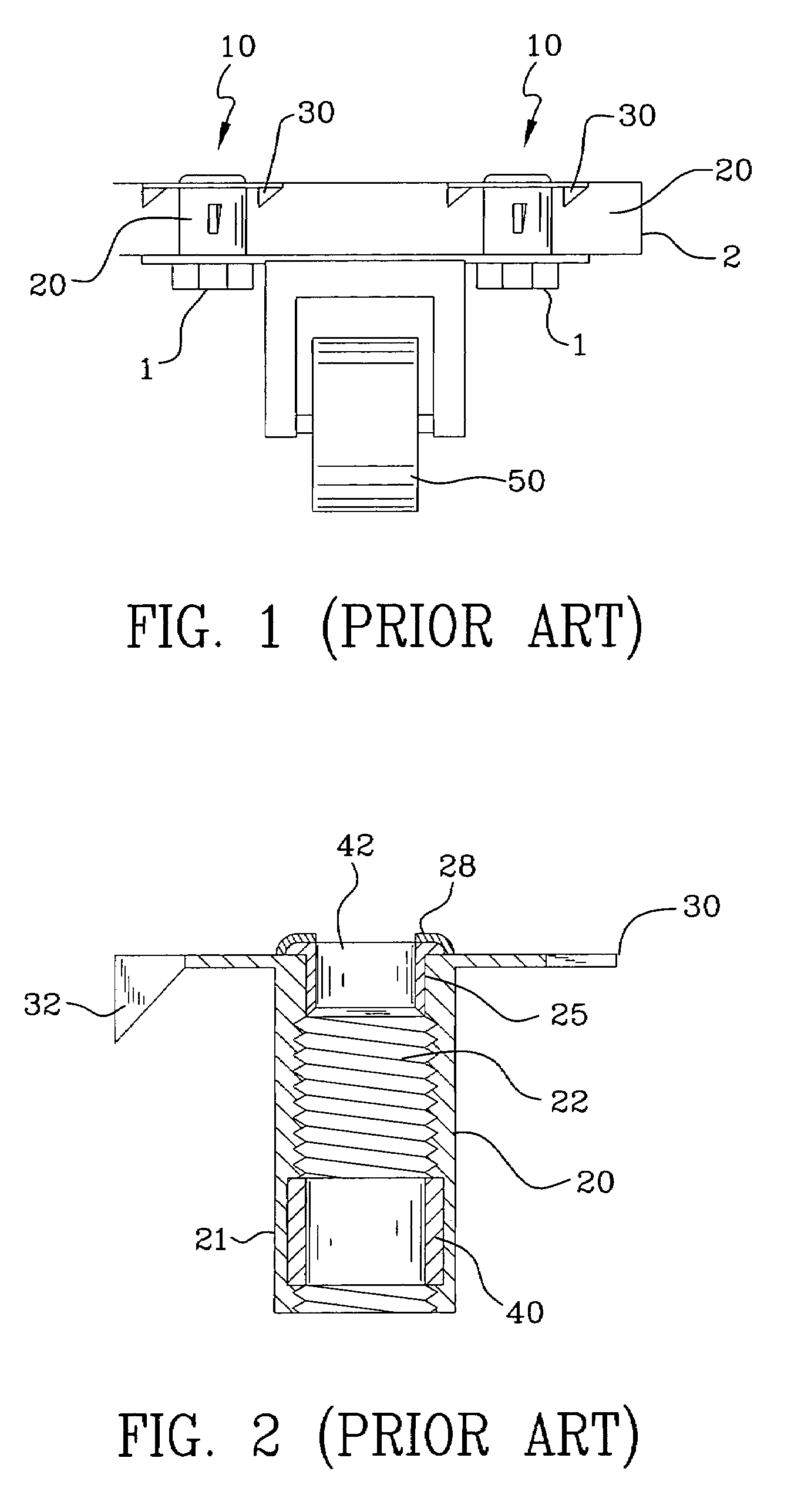
[0037]FIG. 1 is a front view of a prior art tee-nut 1 illustrated in combination with a caster and was described above in connection with the Background Of The Invention above. FIG. 2 is a cross-sectional view of the prior art tee nut of FIG. 1 with the Background Of The Invention above.

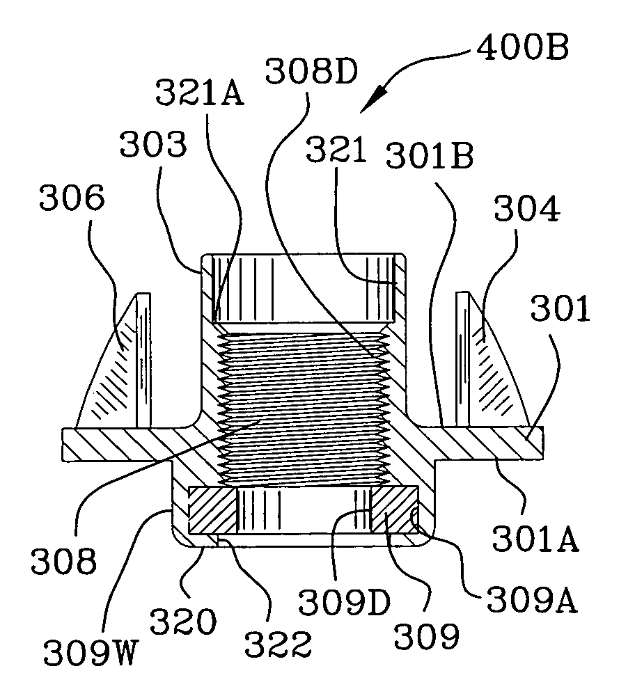
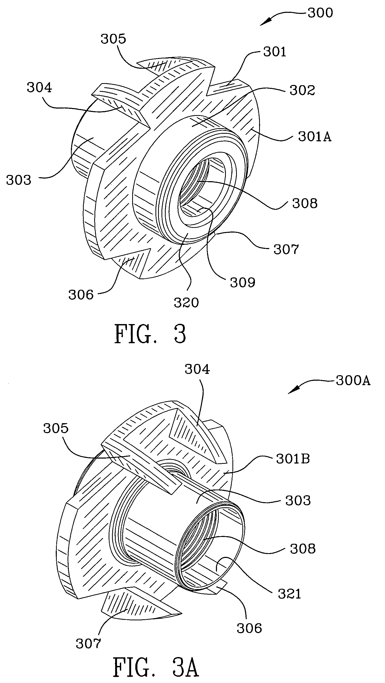
[0038]FIG. 3 is a bottom-side perspective view 300 of the hopper fed tee-nut of the instant invention. The hopper fed tee-nut includes head 320 which is used to guide the tee-nut in a feed track which leads from a hopper (not shown). Head 320 resides within a slot in the hopper feed. Locking ring 309 resides within a lip 320 to the head 302. Head 302 extends perpendicularly away from the bottom side 301A of flange 301. The tee-nut includes teeth 304, 305, 306, and 307 which extend perpendicularly in a direction opposite of the head 302. Teeth 304, 305, 306 and 307 are deformed and extend downwardly away from the flange 301. Reference numeral 301B is used to denote the top side of flange 301B and shan...


PUM


Abstract

A tee-nut fastener which includes a nylon locking ring located distally from the entrance to a passageway ensures proper fastening upon coupling with a threaded stud. The tee-nut is used use in combination with a track for efficient delivery. The track comprises an upper guide spaced apart relatively farther than a lower guide. The process for making the tee nut uses a cold heading process. The tee-nut includes a flange having an upper portion and a lower portion. A shank extends perpendicularly from the upper portion and a head extends oppositely from the shank and perpendicularly from the lower portion. The flange includes at least two teeth extending in the direction of the shank and a passageway through the shank, flange and head. The passageway includes a bore countersunk at both ends thereof, a cavity, and threads therein. A locking ring resides in the cavity and is relatively thin compared to the length of the teeth to ensure that the tee-nut is not extricated from a substrate in which the prongs or teeth are embedded upon coupling with a threaded stud.

Description

FIELD OF THE INVENTION[0001]The invention is in the field of tee-nuts having locks or locking rings to secure a threaded screw or bolt therein.BACKGROUND OF THE INVENTION[0002]U.S. Pat. No. 5,904,461 to McKarge, Jr. discloses a locking tee-nut (T-nut) 10 for securely fastening a threaded element such as a threaded bolt to a structure. FIG. 1 is a front view of a prior art tee-nut illustrated in combination with a caster 50. The tee-nuts 10 are used to secure the frame of the caster to the substrate. The device includes a cylindrical nut body 20 with a threaded bore 22 extending therethrough. The bore 22 has at least one resilient locking ring 40, 42 mounted within an annular groove 25 provided on the inner surface of the bore. A radial flange 30 extends radially from one end of the nut body and includes at least one securing tooth 32 extending therefrom toward the other end of the nut body. Reference numeral 21 denotes the outer surface of the body and reference numeral 28 is an ann...

Claims


Application Information

Patent Timeline
Patent Type & Authority Patents(United States)
IPC IPC(8): F16B37/04F16B39/34
CPCF16B27/00F16B37/048F16B39/34
Inventor SELLE, STEPHEN
Owner STAFAST PROD
Why Eureka
Try Eureka