
Identification of base stations

a technology of identification and base station, applied in the field of wireless communication systems, can solve problems such as creating interference to the carrier, and achieve the effect of facilitating hard hando

Active Publication Date: 2010-03-16
ALCATEL-LUCENT USA INC +1
View PDF9 Cites 3 Cited by
  • Summary
  • Abstract
  • Description
  • Claims
  • Application Information

AI Technical Summary

Benefits of technology

"The patent text describes a method for identifying base stations in compact cells using multiple timing markers, such as PN offsets and phase shifts. This approach increases the number of distinct identification codes without the need for expensive modifications to existing equipment. The method can be expanded by using more than two interval identifications and containing only pilot signals for facilitating hard handoff. The use of multiple PN offsets in a primary carrier creates interference, but the method is able to resolve the time differences associated with base station identification. This allows for the accommodation of proliferation of compact cells with existing equipment."

Problems solved by technology

The use of more than one PN offsets in a primary carrier, i.e., a carrier with active data or voice traffic, creates interference to the carrier.

Method used


Image

  • Identification of base stations
  • Identification of base stations

Examples


Embodiment Construction

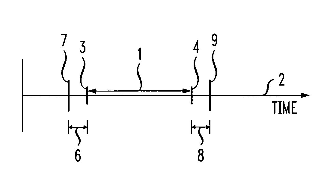
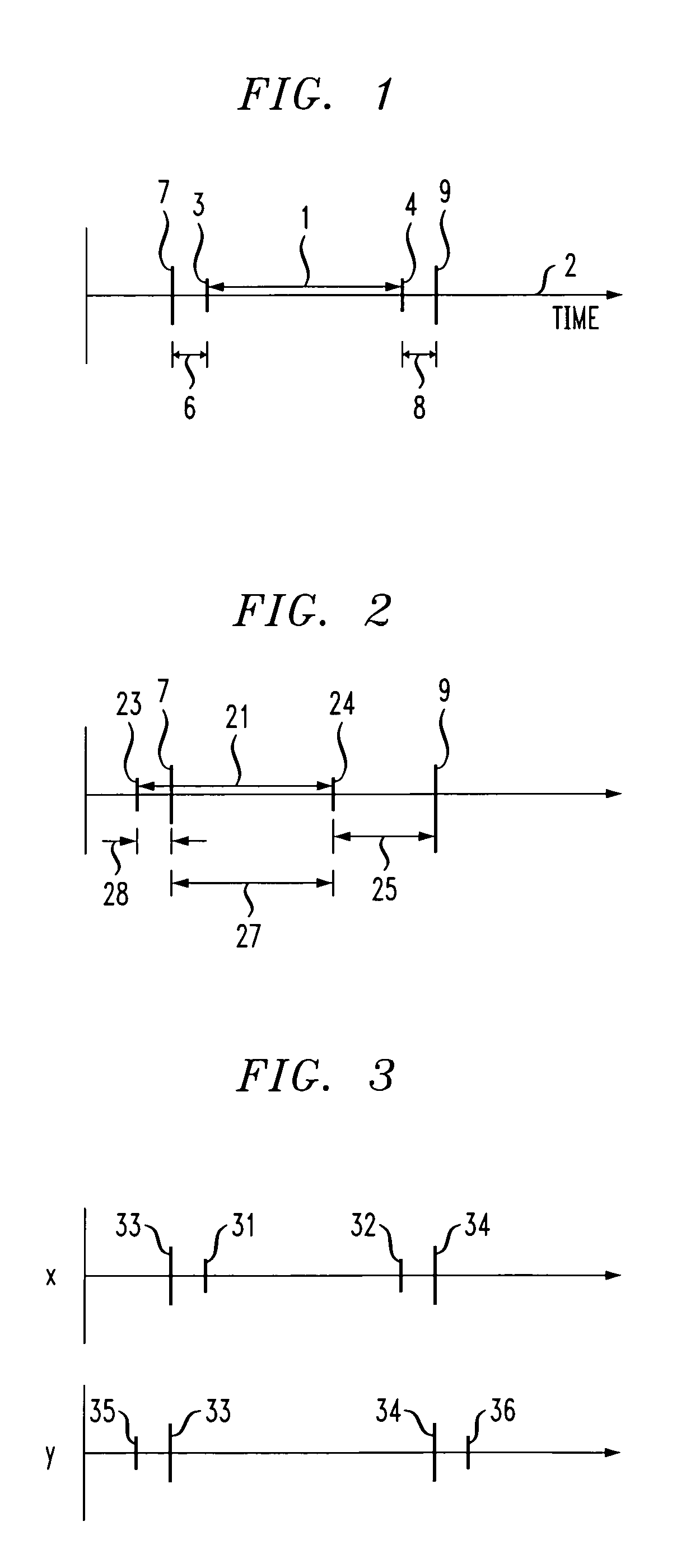
[0016]The identification of base stations in compact cells is accomplished using phase shifts relative to at least one benchmark, preferably at least two benchmarks, of a beacon signal. (The terms phase shift and phase are used interchangeably in the remainder of this disclosure.) For purposes of this invention, a benchmark is a point in time that is specifically identifiable from a repeated transmission pattern. Thus in the example of a CDMA system, exemplary benchmarks are the times at which each PN offset begins. For a UTMS system, exemplary benchmarks are also the beginnings of each data frame. The phase associated with each benchmark is the point in time relative to each benchmark that the pattern of the beacon signal actually begins. To illustrate, in a CDMA system the beginning of a two second time interval is marked by a global positioning satellite (GPS) signal. As previously discussed, such two second interval is divided into seventy-five 26-⅔ millisecond divisions. Each d...


PUM


Abstract

The identification of wireless communication base stations in a region of high base station density is effected using a specific identification signal pattern transmitted by the base stations. In particular, each base station transmits a signal having a pattern with at least two time phase shifts relative to at least one time benchmark. The combination of these phase shifts allows identification of the transmitting base station. Since a plurality of phase shifts leads to a concomitantly larger number of phase shift combinations, the capacity to identify base stations is enlarged.

Description

CROSS-REFERENCE TO RELATED APPLICATION[0001]This application is related to U.S. patent application Ser. No. 11 / 435,665 (De Lind Van Wijngaarden 15-19-15-21-5-3-64-10) filed May 17, 2006 (concurrently herewith) and is hereby incorporated by reference in its entirety.TECHNICAL FIELD[0002]This invention relates to wireless communication systems and in particular wireless communication systems that require identification of base stations.BACKGROUND OF THE INVENTION[0003]A wireless network generally is divided into a multiplicity of cells with each cell having at least one base station. A user within the cell wishing to send information establishes communication with a base station in the cell. This receiving base station communicates typically with a mobile switching center (MSC), another base station, or another network entity that, in turn, relays the information through the network to the central office or base station in the cell where the intended recipient is located.[0004]A varie...

Claims


Application Information

Patent Timeline
Patent Type & Authority Patents(United States)
IPC IPC(8): H04W4/00H04W48/08H04W48/16
CPCH04B1/7083H04W48/08H04B2201/70702H04J13/0029H04W48/16
Inventor MA, ZHENGXIANGPOLAKOS, PAUL ANTHONY
Owner ALCATEL-LUCENT USA INC
Learn More