Image processing apparatus and method thereof
a technology of image processing and image, applied in the direction of colour separation/tonal correction, digital marking record carriers, instruments, etc., can solve the problems of incongruity, inability to accurately calculate methods, and limit of density values to 100%, so as to achieve accurate color reproduction
- Summary
- Abstract
- Description
- Claims
- Application Information
AI Technical Summary
Benefits of technology
Problems solved by technology
Method used
Image
Examples
first embodiment
[Arrangement of Printing Server]
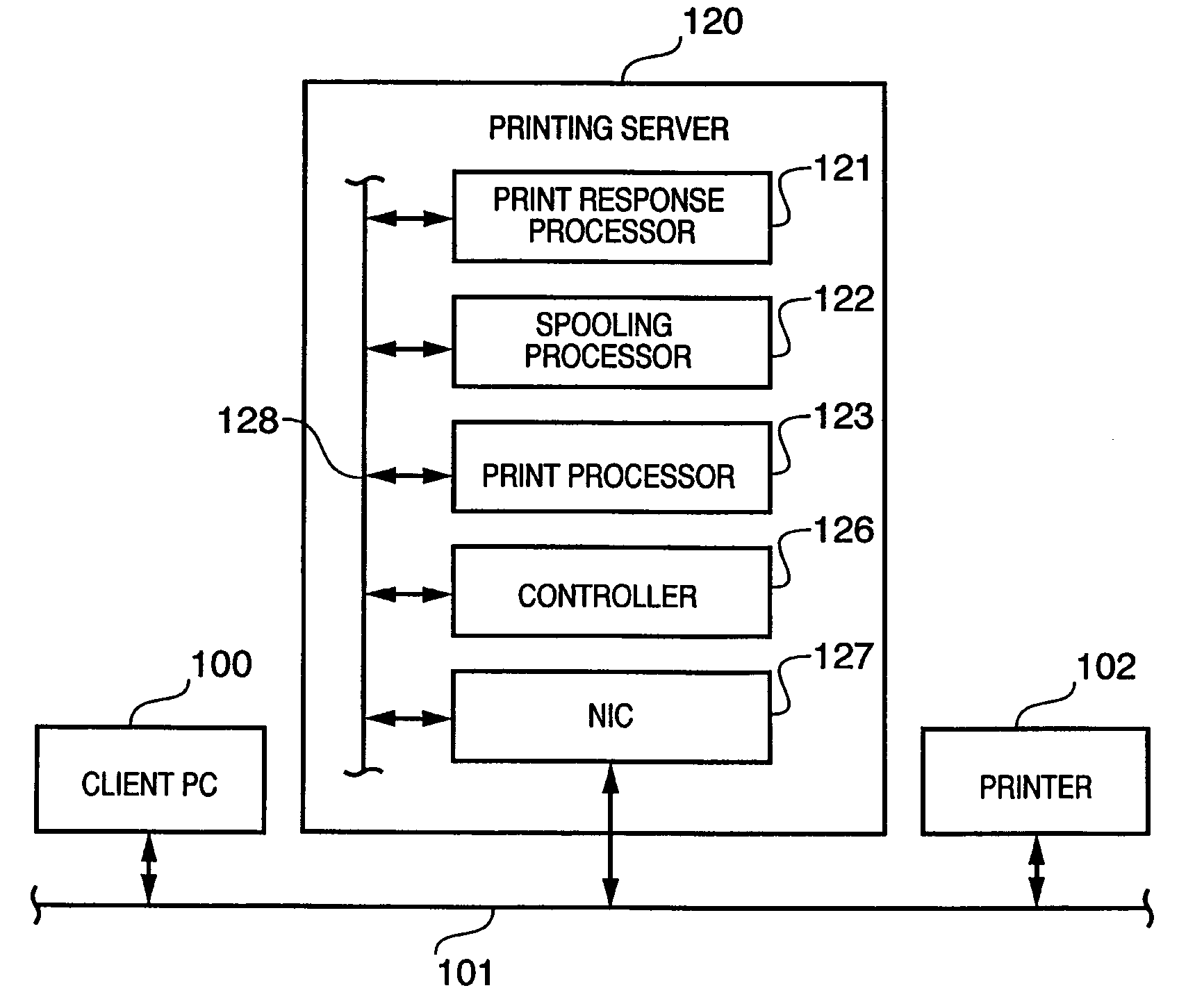
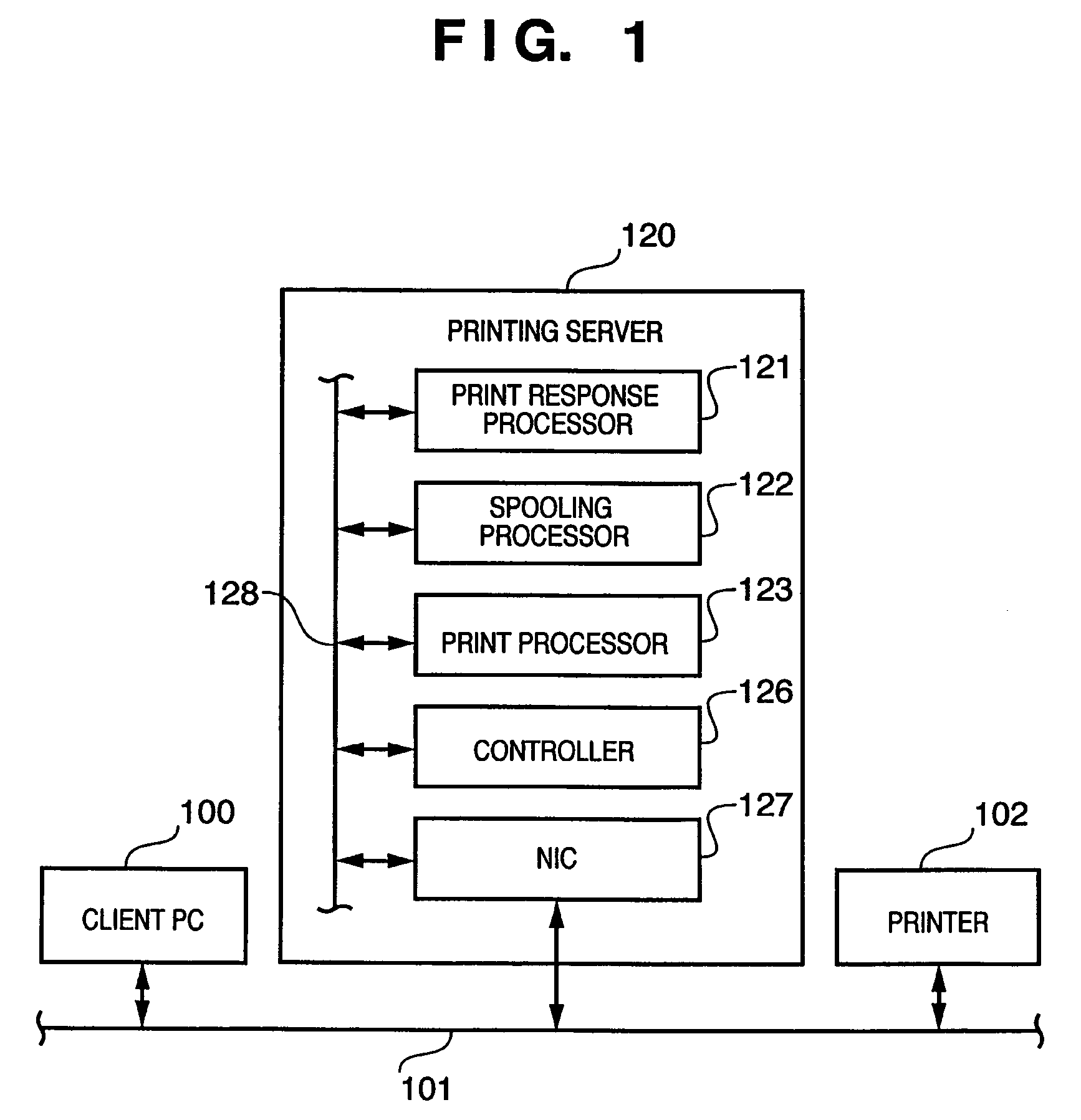
[0035]FIG. 1 is a block diagram showing the arrangement of a printing server of this embodiment.
[0036]A printing server 120 can be implemented by, e.g., supplying software that executes processing to be described later to a computer apparatus which has a CPU, RAM, and ROM. Of course, the printing server 120 can also be implemented by forming functional blocks to be described later by hardware components, and combining these functional blocks.
[0037]The printing server 120 connects a network 101 via a network interface card (NIC) 127, and receives data (to be referred to as “PDL data” hereinafter) which includes spot color information and is described using a page (or band) description language from a client PC 100. Output data of a CMYK value obtained by rendering the PDL data is sent to a printer 102 to execute print processing. Note that the printing server 120 outputs data of a CMYK value when color calibration is made using the printer 102, but it ...
second embodiment
[0062]Image processing according to the second embodiment of the present invention will be described below. Note that the same reference numerals in the second embodiment denote the same components as in the first embodiment, and a detailed description thereof will be omitted.
[Calculation of Composite Spot Color]
[0063]FIG. 8 is a diagram for explaining an overview of the processing of the second embodiment, i.e., a diagram for explaining processing for obtaining a color value of a composite color of two spot colors.
[0064]Two spot color data (e.g., the names of orange, green, red, and the like, Munsel numbers, PANTONE® names, and the like) are input to a spectral reflectance calculator 1101. The spectral reflectance calculator 1101 obtains matched spectral reflectance data (to be referred to as “spectral data” hereinafter) from a spot color database (DB) 1102, and calculates a spectral reflectance of a composite color of the two spot colors. A color value calculator 1103 converts spe...
third embodiment
[0083]Image processing according to the third embodiment of the present invention will be described below. Note that the same reference numerals in the third embodiment denote the same components as in the first and second embodiments, and a detailed description thereof will be omitted.
[Arrangement of Printing Server]
[0084]FIG. 14 is a block diagram showing the arrangement of a printing server of the third embodiment.
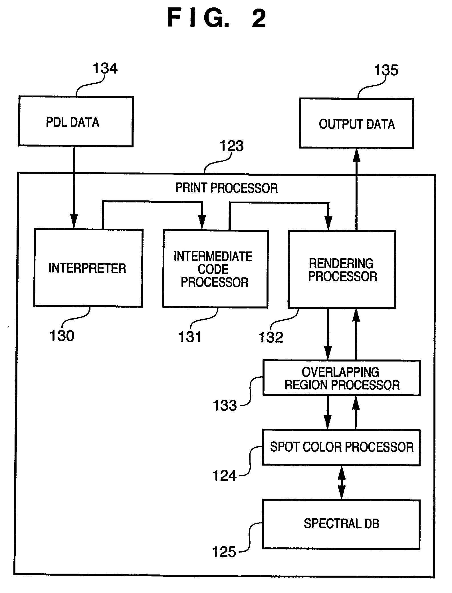
[0085]The print processor 123 interprets readout PDL data to convert it into intermediate code data, applies required processing, e.g., sort processing, imposition processing, and the like, renders the intermediate code data, and outputs the rendered data as output data such as a CMYK value or the like. In this case, the print processor 123 checks objects such as text, line image, picture, table, and the like of the input intermediate code data, and controls an overlapping region processor 1125 to process an overlapping portion of objects (overlapping region).
[0086]The ...
PUM
| Property | Measurement | Unit |
|---|---|---|
| wavelength | aaaaa | aaaaa |
| reflectance | aaaaa | aaaaa |
| reflectance | aaaaa | aaaaa |
Abstract
Description
Claims
Application Information
 - R&D
- Intellectual Property
- Life Sciences
- Materials
- Tech Scout
- Unparalleled Data Quality
- Higher Quality Content
- 60% Fewer Hallucinations
Browse by: Latest US Patents, China's latest patents, Technical Efficacy Thesaurus, Application Domain, Technology Topic, Popular Technical Reports.
© 2025 PatSnap. All rights reserved.Legal|Privacy policy|Modern Slavery Act Transparency Statement|Sitemap|About US| Contact US: help@patsnap.com


