Light-emitting display device-equipped rear-view mirror

a technology of light-emitting display device and rear-view mirror, which is applied in the direction of optical viewing, vehicle components, instruments, etc., can solve problems such as poor visibility, and achieve the effect of reducing stress

Active Publication Date: 2010-04-13
MURAKAMI CORP
View PDF15 Cites 123 Cited by
  • Summary
  • Abstract
  • Description
  • Claims
  • Application Information

AI Technical Summary

Benefits of technology

[0008]The present invention comprises: a mirror element having a semi-transmissive reflective film on one surface of a transparent substrate; a mask member having an opening in a surface thereof, the mask member being arranged over an entire region excluding the opening, or at a relevant region excluding the opening, of a back side of the mirror element, at least a front surface of the mask member being of a dark color; and a light-emitting display device arranged at a position behind the mirror element, with a display surface facing the opening of the dark color mask member, wherein the orientation of a central axis of the display surface of the light-emitting display device is inclined toward a driver's viewpoint relative to the orientation of a central axis of the mirror element. According to the present invention, the orientation of the central axis of the display surface of the light-emitting display device is inclined toward the driver's viewpoint relative to the orientation of the central axis of the mirror element, making it easier for the driver to see indications. Also, since the reflective film is formed of a semi-transmissive reflective film, the display region can also function as a mirror when no indications are displayed (i.e., where the lights are off).
[0009]In the present invention, where the mirror element is formed of a plane mirror, it is possible that: the display surface of the light-emitting display device is arranged at the position of the opening in such a manner that it is inclined toward the driver's viewpoint relative to a surface of the mirror element; and a periphery of a wedge-shaped gap occurring between the mirror element and the light-emitting display device due to the inclination is occluded by a wall member, at least an inner surface of the wall member being of a dark color. This configuration makes it easier for the driver to see indications, and also to prevent the inside of the mirror device from being seen through from the wedge-shaped gap occurring between the mirror element and the light-emitting display device by occluding the gap with the wall member.
[0011]In the present invention, it is possible that the semi-transmissive reflective film is made of, for example, a dielectric multilayer film. Also, it is possible that a reflection peak wavelength of the mirror element in a visible light range is set to, for example, from 500 to 550 nm. As a result of setting the reflection characteristic as stated above, the reflected light intensity for both bluish short wavelength range light from a discharge lamp and reddish long wavelength range light from a halogen lamp can be reduced, making it possible to obtain a glare prevention effect during nighttime driving. The reflection color according to this reflection characteristic turns to be a greenish color, which is deemed to be eye-friendly, as a result of reduction of blue, which is highly irritating, making it possible to reduce stress given to the driver due to reflected light during daytime driving.

Problems solved by technology

Typically, a rear-view mirror is used with the mirror oriented outward relative to the direction toward the driver's viewpoint, and accordingly, when the orientation of the display surface of the light-emitting display device is set to be the same as the orientation of the mirror, the display surface is not oriented toward the driver, which results in poor visibility.

Method used


Image

  • Light-emitting display device-equipped rear-view mirror
  • Light-emitting display device-equipped rear-view mirror
  • Light-emitting display device-equipped rear-view mirror

Examples


embodiment 1

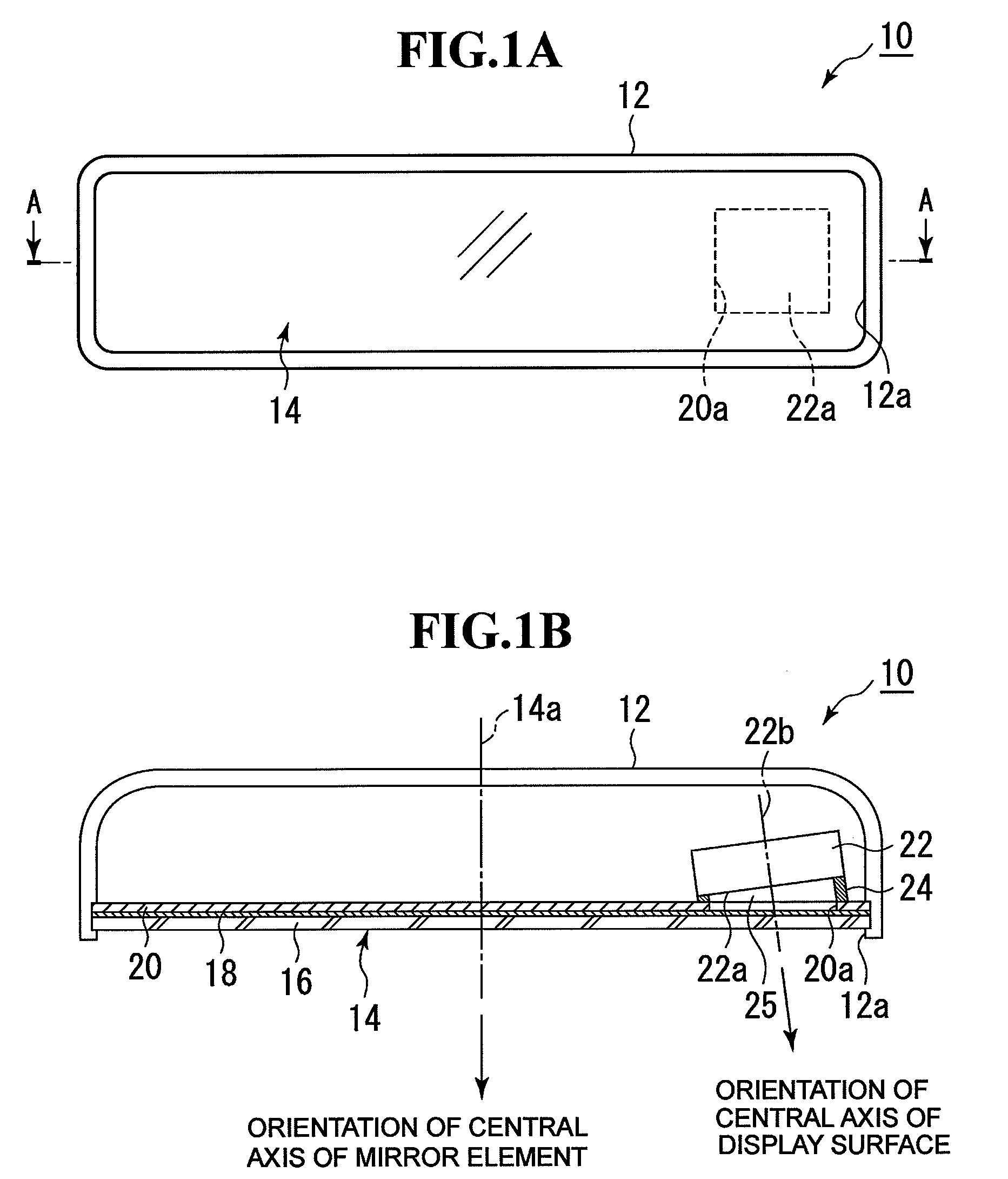
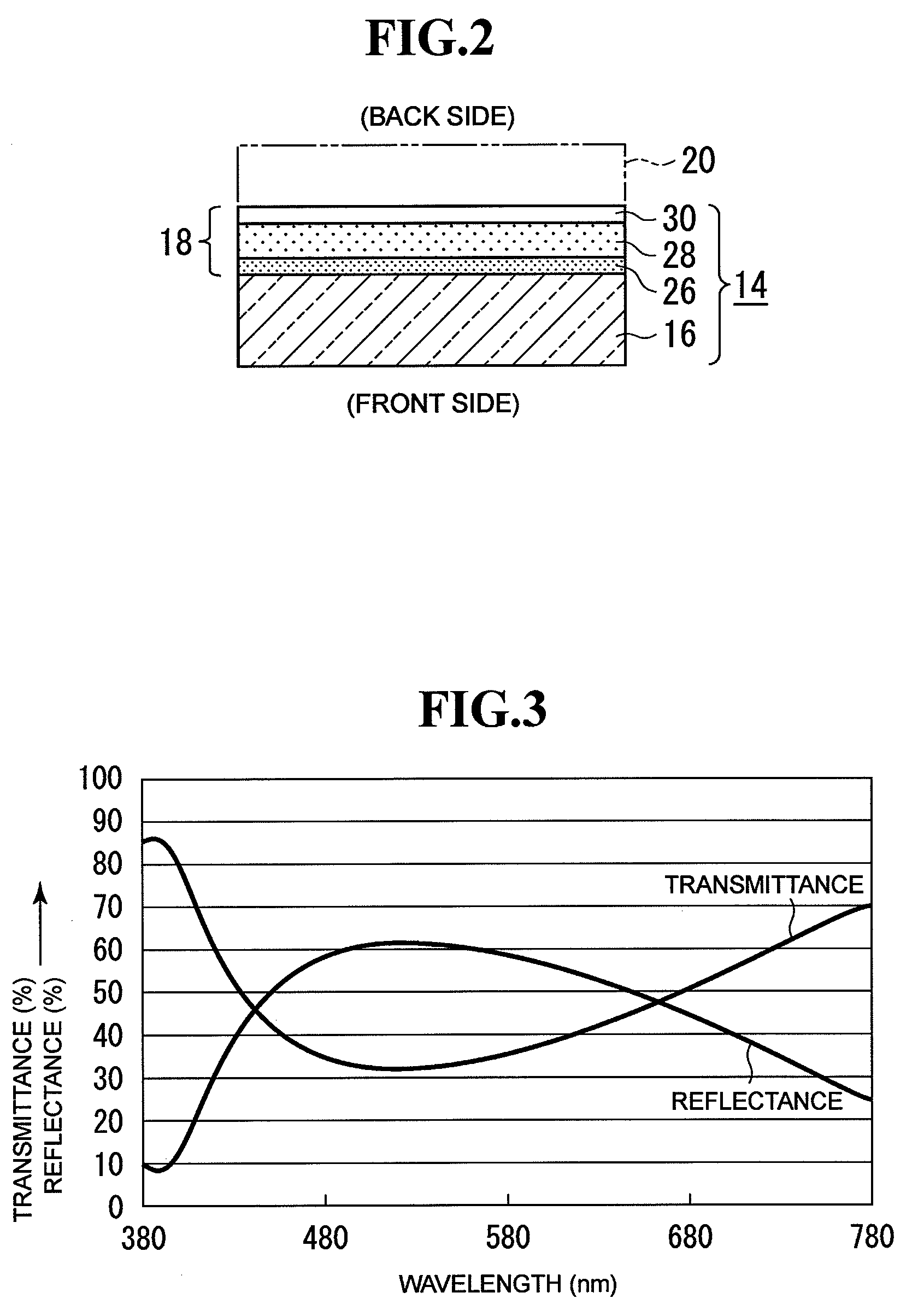
[0020]Embodiment 1 of the present invention will be described. FIGS. 1A and 1B illustrate an overview of the inner structure of a vehicle inner mirror to which the present invention has been applied. This embodiment has a mirror element formed of a plane mirror. FIG. 1A is a front view, and FIG. 1B is a cross-sectional view taken along a line indicated by arrows A-A in FIG. 1A. An inner mirror 10 is formed by putting a mirror element 14 into a front opening 12a of a housing 12. The mirror element 14 is formed to be a plane mirror having a semi-transmissive reflective film 18, which is formed of a dielectric multilayer film, on the back surface of a transparent substrate 16, such as flat plate-shaped glass. A dark color (for example, black) mask member 20 is attached to the back surface of the mirror element 14. An opening 20a is formed at the relevant region of the dark color mask member 20 (in FIGS. 1A and 1B, the right corner of the surface of the mirror element 14 close to a driv...

embodiment 2

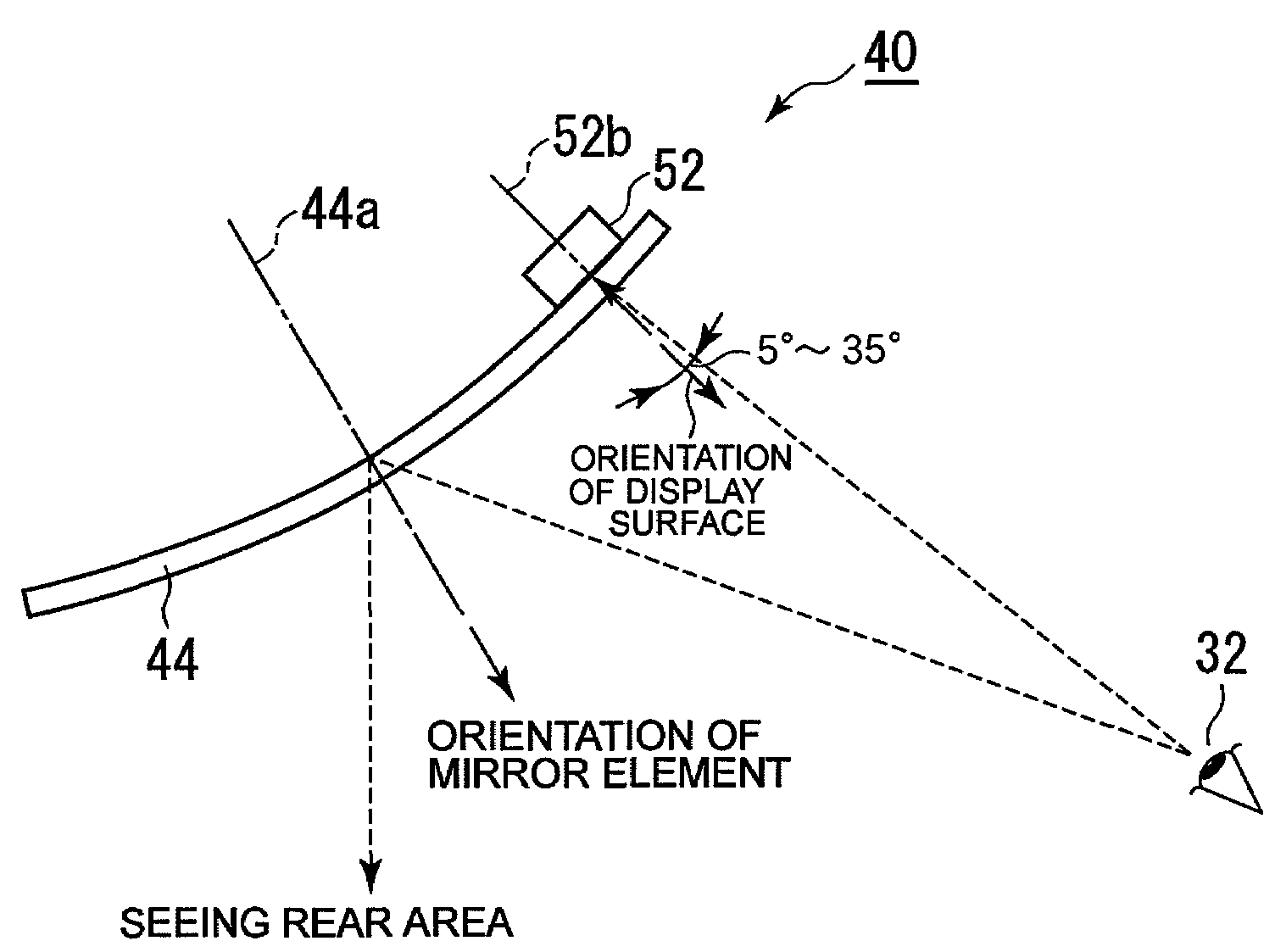
[0024]Embodiment 2 of the present invention will be described. FIGS. 6A and 6B illustrate an overview of the inner structure of a vehicle inner mirror to which the present invention has been applied. This embodiment has a mirror element formed of a convex mirror. FIG. 6A is a front view, and FIG. 6B is a cross-sectional view taken along a line indicated by arrows B-B in FIG. 6A. An inner mirror 40 is formed by putting a mirror element 44 into a front opening 42a of a housing 42. The mirror element 44 is formed to be a convex mirror having a semi-transmissive reflective film 48, which is formed of a dielectric multilayer film, on the back surface of a transparent substrate 46 such as curved glass. The semi-transmissive reflective film 48 can have the film configuration that is similar to that shown in FIG. 2 and can also have the reflectance characteristics and transmittance characteristics that are similar to those shown in FIG. 3. The curvature radius of the curve can be set to, fo...


PUM


Abstract

Visibility of indications in a rear-view mirror incorporating a light-emitting display device is improved. A mirror element is formed by forming a semi-transmissive reflective film on one surface of a transparent substrate. On a back surface of the mirror element, a dark color mask member is arranged. An opening is formed in the mask member. Behind the mirror element, a light-emitting display device is arranged facing the opening. Where the mirror element is formed of a plane mirror, the light-emitting display device is arranged in such a manner that it is inclined toward a driver relative to the mirror surface. A wedge-shaped gap occurring between the mirror element and the light-emitting display device due to the inclination is occluded by a wall member. Where the mirror element is formed of a convex mirror, the opening is formed at a corner of the surface of the mirror element close to the driver, and the light-emitting display device is arranged facing an opening, with a display surface arranged in parallel to the surface of the mirror element 44.

Description

[0001]The disclosure of Japanese Patent Application No. JP2007-300380 filed on Nov. 20, 2007 including the specification, drawing and abstract is incorporated herein by reference in its entirety.BACKGROUND OF THE INVENTION[0002]1. Field of the Invention[0003]The present invention relates to a rear-view mirror incorporating a light-emitting display device, and specifically relates to one with improved indication visibility.[0004]2. Description of the Related Art[0005]Japanese Patent Laid-Open No. 2000-255321, Japanese Patent No. 3846073, Japanese Patent Laid-Open No. 2005-316509, and Japanese Patent Laid-Open No. 2003-267129 each disclose a rear-view mirror that incorporates a light-emitting display device to display various kinds of information.[0006]According to the rear-view mirror disclosed in each of Japanese Patent Laid-Open No. 2000-255321, Japanese Patent No. 3846073, Japanese Patent Laid-Open No. 2005-316509, and Japanese Patent Laid-Open No. 2003-267129, the orientation of ...

Claims


Application Information

Patent Timeline
Patent Type & Authority Patents(United States)
IPC IPC(8): B60R1/08
CPCB60R1/12B60R2001/1253B60R2001/1215
Inventor TAKAYANAGI, SHINYANAKAMURA, MASATOSHIMOTOMIYA, MASAHIRO
Owner MURAKAMI CORP
Why Eureka
Try Eureka