Exhaust emission control device of internal combustion engine
an emission control device and internal combustion engine technology, applied in the direction of electric control, machines/engines, mechanical equipment, etc., can solve the problems of deteriorating driving comfort and reduce torque shock, and achieve high accuracy without affecting driving comfor
- Summary
- Abstract
- Description
- Claims
- Application Information
AI Technical Summary
Benefits of technology
Problems solved by technology
Method used
Image
Examples
first embodiment
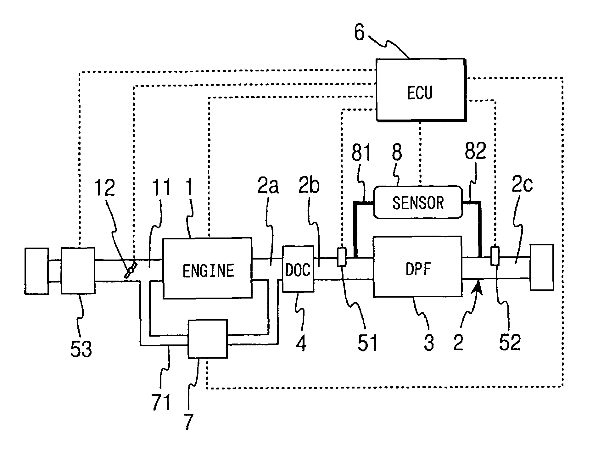
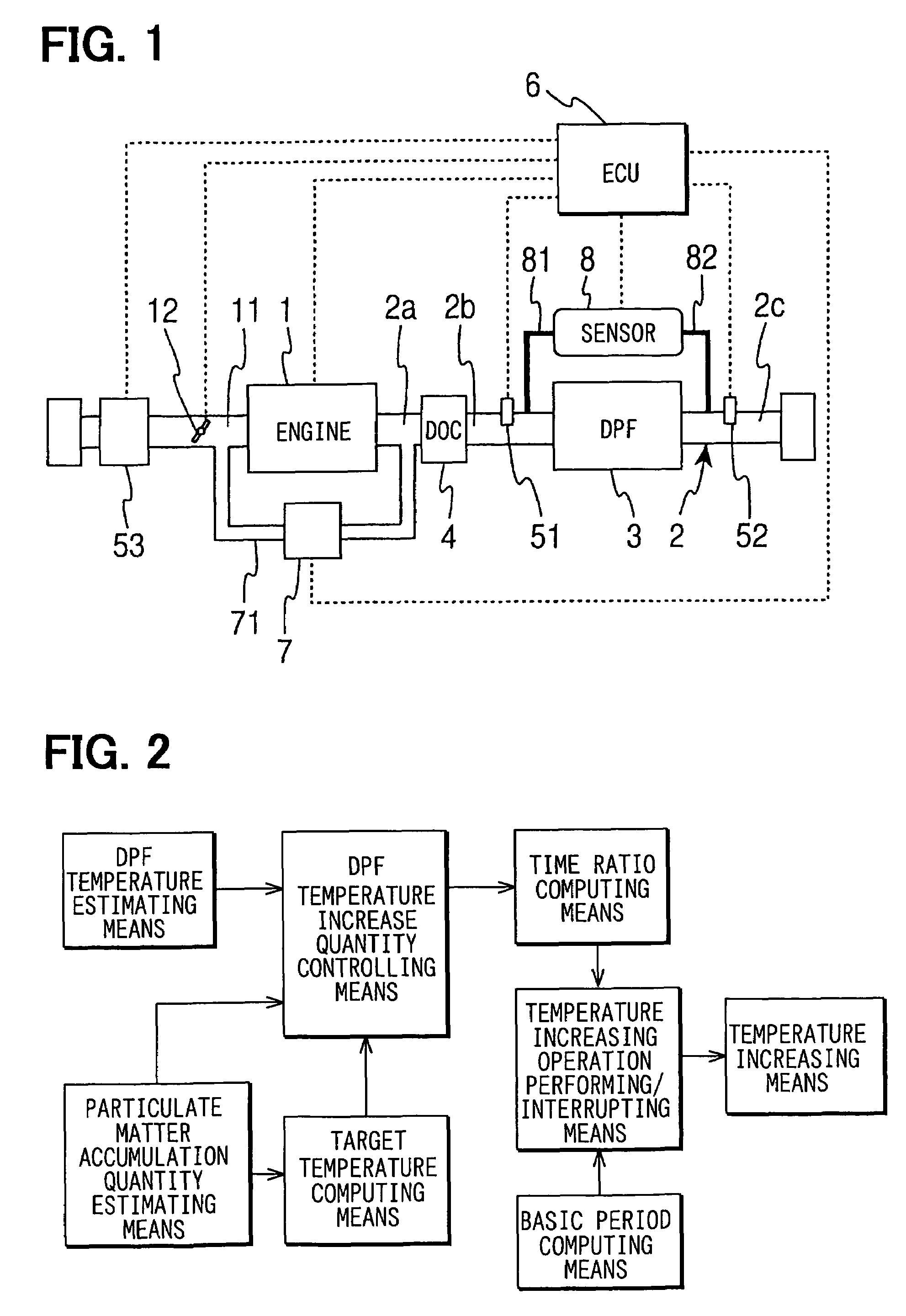
[0071]the regeneration control of the DPF 3 by the ECU 6 is shown in FIGS. 13, 14. FIG. 13 is a flow chart for computing the time ratio D between the performance and interruption of a temperature increasing operation by the temperature increasing means. First, at Step 101, the ECU 6 reads exhaust temperatures T1, Ts from the exhaust temperature sensors 51, 52 disposed upstream and downstream of the DPF 3. At Step 102, the ECU 6 computes a DPF estimation temperature T based on the exhaust temperatures T1, T2 upstream and downstream of the DPF 3. Here, the ECU 6 computes the DPF estimation temperature T from the exhaust temperatures T1, T2 but, for simplicity, it is also possible to let T=T1 or T=T2. At Step 103, the ECU 6 estimates the quantity of PM accumulated in the DPF 3. For example, the quantity of accumulated PM can be estimated based on the pressure difference across the DPF 3 sensed by the pressure difference sensor 8 and the flow rate of exhaust gas computed from the output...
second embodiment
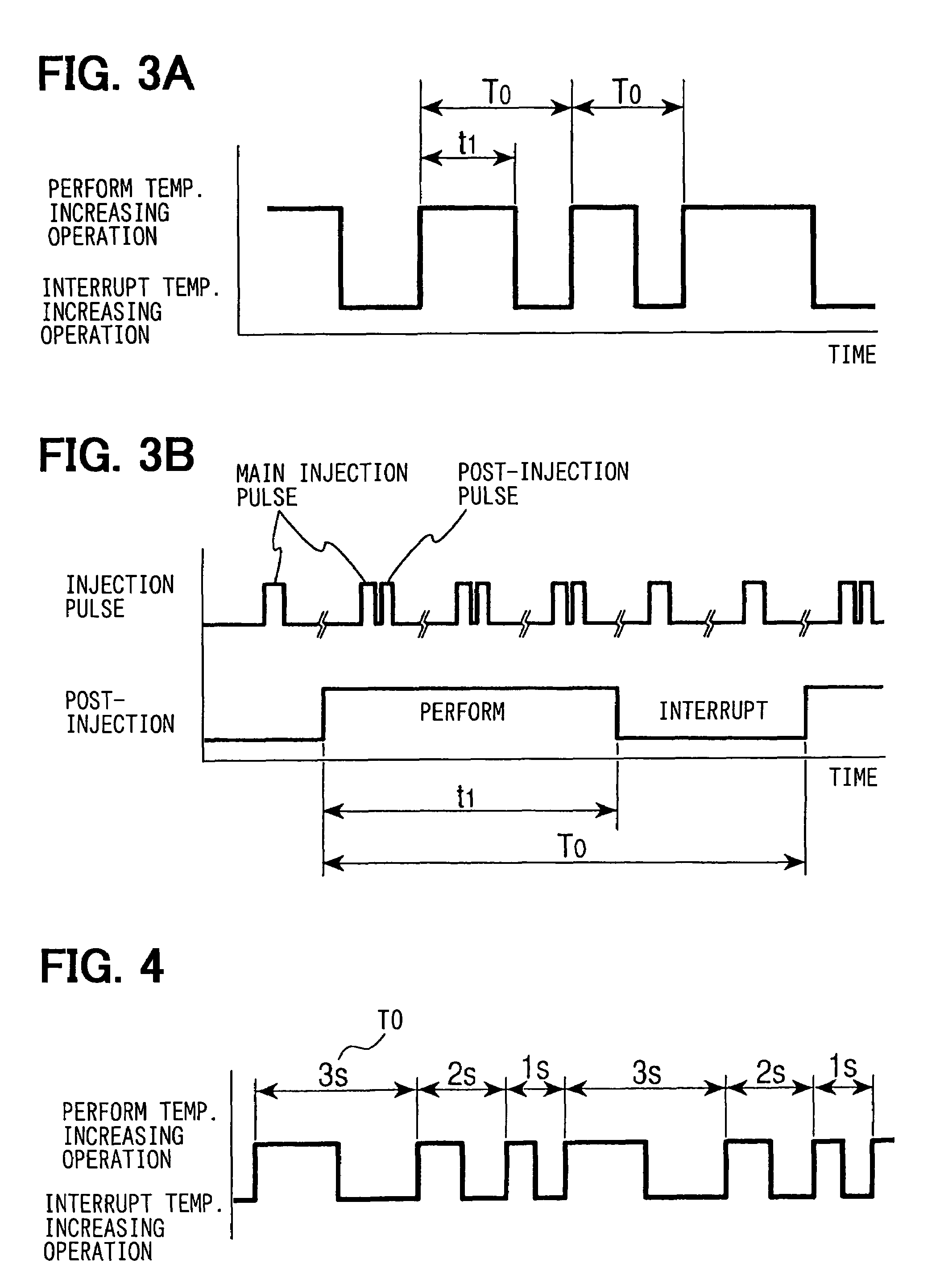
[0082]FIG. 17 is a flow chart showing the invention. The basic flow of the regeneration control is the same as shown in FIG. 13 and hence a method of changing a period of performing and interrupting the temperature increasing operation within the base period T0 will be mainly described. In FIG. 17, first, the ECU 6 determines at Step 301 whether or not the regeneration control performance flag Flag1 is ON. If negative determination is made at Step 301, variables to be used in this flow are initialized (base period T0 of time ratio D, T0=1, temperature increase counter C2=5) and the temperature increasing operation flag Flag2 is set OFF and this processing is finished. If affirmative determination is made at Step 301, the routine proceeds to Step 302.
[0083]At Step 302, it is determined whether or not the base period T0 is to be updated. To be specific, it is determined whether or not the temperature increase counter C2 is larger than the base period T0. If it is determined that C2>T0...
third embodiment
[0087]FIG. 20 is a flow chart showing the invention. In this embodiment, a method for correcting the state of fuel injection from a change in the engine speed caused by switching the temperature increasing operation when the regeneration control is performed will be described. In FIG. 20, first, the ECU 6 determines at Step 401 whether or not the regeneration control performance flag Flag1 is ON. If negative determination is made at Step 401, variables to be used in this flow are initialized (engine speed NEON when the temperature increasing operation is performed=NE, engine speed NEOFF when the temperature increasing operation is interrupted=NEOFF, and integral quantity Hi=0), and the processing is finished. If affirmative determination is made at Step 401, the routine proceeds to Step 402.
[0088]At Step 402, engine speed NE, injection quantity of Q (substitute for torque), and time ratio D between the performance and interruption of the temperature increasing operation are read. At...
PUM
 Abstract
Description
Claims
Application Information
 - R&D
- Intellectual Property
- Life Sciences
- Materials
- Tech Scout
- Unparalleled Data Quality
- Higher Quality Content
- 60% Fewer Hallucinations
Browse by: Latest US Patents, China's latest patents, Technical Efficacy Thesaurus, Application Domain, Technology Topic, Popular Technical Reports.
© 2025 PatSnap. All rights reserved.Legal|Privacy policy|Modern Slavery Act Transparency Statement|Sitemap|About US| Contact US: help@patsnap.com


