Exhaust emission control device of internal combuston engine

a technology of exhaust emission control and internal combustion engine, which is applied in the direction of electric control, machines/engines, mechanical equipment, etc., can solve the problems of deteriorating driving comfort and improve driving comfort, and achieve the effect of reducing torque shock and high accuracy

Inactive Publication Date: 2005-11-10
DENSO CORP
View PDF15 Cites 24 Cited by
  • Summary
  • Abstract
  • Description
  • Claims
  • Application Information

AI Technical Summary

Benefits of technology

[0009] Therefore, the present invention reduces torque shock caused by switching between a state in which fuel is injected to increase temperature (temperature increasing operation is performed) and a state in which fuel is injected normally (temperature increasing operation is interrupted) during the regeneration of the DPF and to perform a control of increasing the temperature of a DPF with high accuracy without impairing drivability.

Problems solved by technology

When periodic torque shock transmitted to the driver occurs continuously, drivability deteriorates.

Method used


Image

  • Exhaust emission control device of internal combuston engine
  • Exhaust emission control device of internal combuston engine
  • Exhaust emission control device of internal combuston engine

Examples


first embodiment

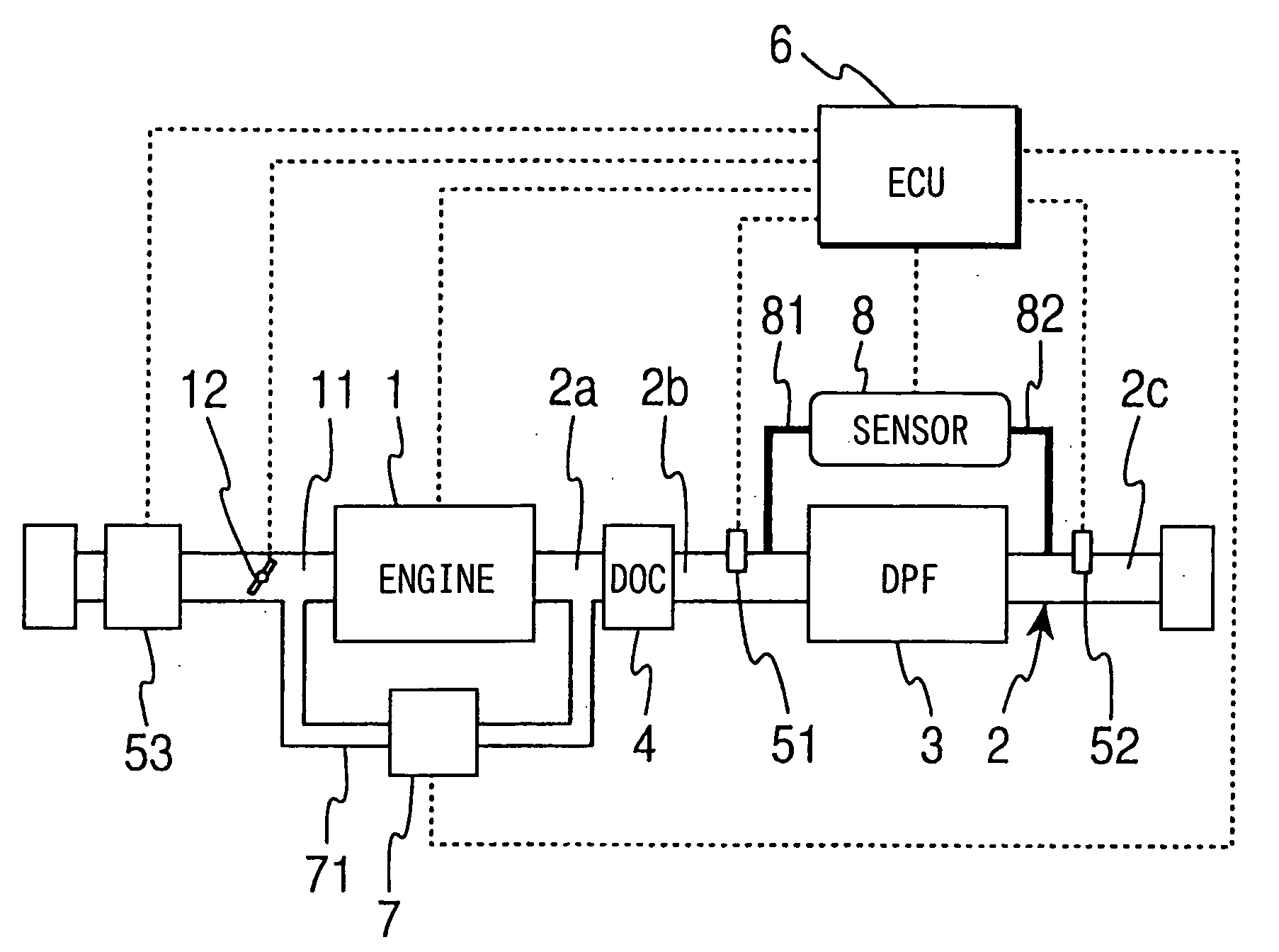
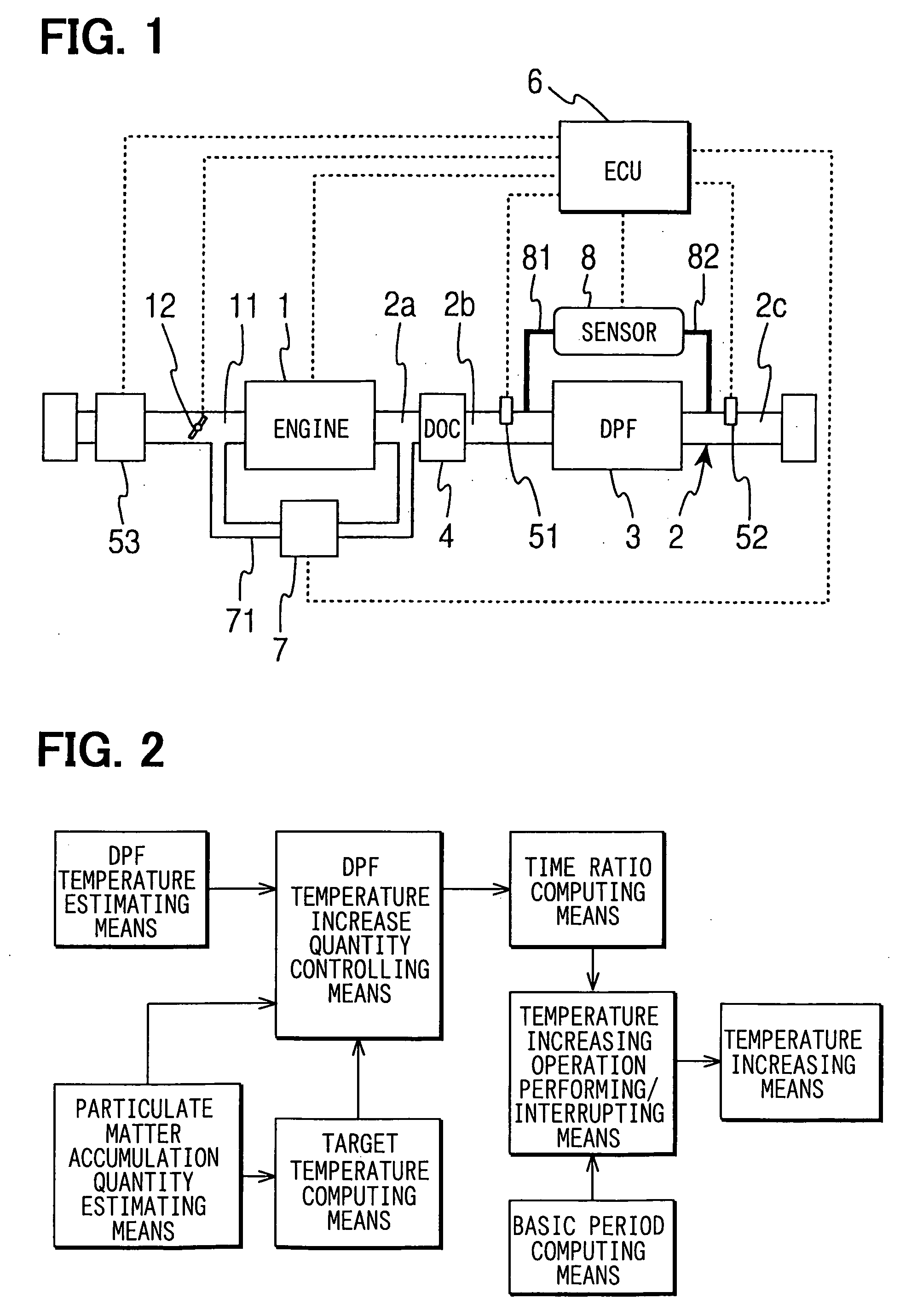
[0071] the regeneration control of the DPF 3 by the ECU 6 is shown in FIGS. 13, 14. FIG. 13 is a flow chart for computing the time ratio D between the performance and interruption of a temperature increasing operation by the temperature increasing means. First, at Step 101, the ECU 6 reads exhaust temperatures T1, Ts from the exhaust temperature sensors 51, 52 disposed upstream and downstream of the DPF 3. At Step 102, the ECU 6 computes a DPF estimation temperature T based on the exhaust temperatures T1, T2 upstream and downstream of the DPF 3. Here, the ECU 6 computes the DPF estimation temperature T from the exhaust temperatures T1, T2 but, for simplicity, it is also possible to let T=T1 or T=T2. At Step 103, the ECU 6 estimates the quantity of PM accumulated in the DPF 3. For example, the quantity of accumulated PM can be estimated based on the pressure difference across the DPF 3 sensed by the pressure difference sensor 8 and the flow rate of exhaust gas computed from the outpu...

second embodiment

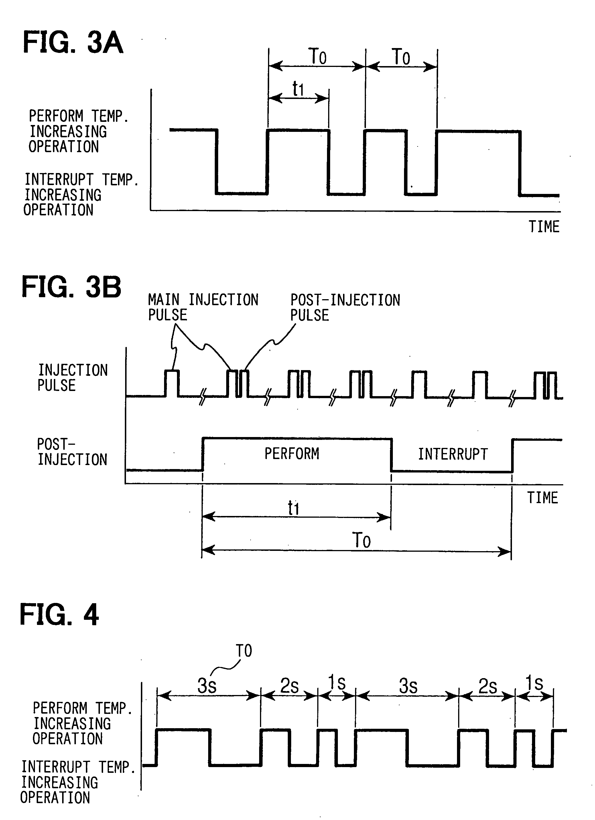
[0082]FIG. 17 is a flow chart showing the invention. The basic flow of the regeneration control is the same as shown in FIG. 13 and hence a method of changing a period of performing and interrupting the temperature increasing operation within the base period T0 will be mainly described. In FIG. 17, first, the ECU 6 determines at Step 301 whether or not the regeneration control performance flag Flag1 is ON. If negative determination is made at Step 301, variables to be used in this flow are initialized (base period T0 of time ratio D, T0=1, temperature increase counter C2=5) and the temperature increasing operation flag Flag2 is set OFF and this processing is finished. If affirmative determination is made at Step 301, the routine proceeds to Step 302.

[0083] At Step 302, it is determined whether or not the base period T0 is to be updated. To be specific, it is determined whether or not the temperature increase counter C2 is larger than the base period T0. If it is determined that C2>T...

third embodiment

[0087]FIG. 20 is a flow chart showing the invention. In this embodiment, a method for correcting the state of fuel injection from a change in the engine speed caused by switching the temperature increasing operation when the regeneration control is performed will be described. In FIG. 20, first, the ECU 6 determines at Step 401 whether or not the regeneration control performance flag Flag1 is ON. If negative determination is made at Step 401, variables to be used in this flow are initialized (engine speed NEON when the temperature increasing operation is performed=NE, engine speed NEOFF when the temperature increasing operation is interrupted=NEOFF, and integral quantity Hi=0), and the processing is finished. If affirmative determination is made at Step 401, the routine proceeds to Step 402.

[0088] At Step 402, engine speed NE, injection quantity of Q (substitute for torque), and time ratio D between the performance and interruption of the temperature increasing operation are read. A...


PUM


Abstract

An exhaust emission control device includes a plurality of means for removing particulates accumulated in a particulate filter. A temperature increasing means increases a temperature of the particulate filter. A temperature estimating means estimates the temperature of the particulate filter. A particulate accumulation quantity estimating means estimates a quantity of accumulated particulates. A temperature increase quantity controlling means controls a temperature increase to an output of the temperature estimating means when the quantity of accumulated particulates exceeds a predetermined value. A time ratio computing means computes a time ratio between performance and interruption of a temperature increasing operation. A base period computing means computes a period that becomes a base of the time ratio such that the period varies as required. A switching means switches between performance and interruption of the temperature increasing operation based on the time ratio and the period that becomes the base.

Description

CROSS REFERENCE TO RELATED APPLICATIONS [0001] This application is based upon and claims the benefit of priority of Japanese Patent Application No. 2004-139915, filed on May 10, 2004, the contents of which are incorporated herein by reference. FIELD OF THE INVENTION [0002] The present invention relates to an exhaust emission control device of an internal combustion engine having a particulate filter disposed in an exhaust passage for improving drivability during a temperature increase regeneration of the particulate filter. BACKGROUND OF THE INVENTION [0003] In recent years, an exhaust emission control device, which treats exhaust gas discharged from an internal combustion engine with a catalyst or a filter to reduce the discharge of toxic components, has gained importance as an environmental protection measure. For example, an exhaust emission control device has been known in which a diesel particulate filter (hereinafter referred to as “DPF”) is disposed in an exhaust pipe to coll...

Claims


Application Information

Patent Timeline
Patent Type & Authority Applications(United States)
IPC IPC(8): F01N3/00F01N3/02F02D45/00F01N3/023F01N3/025F01N3/029F01N9/00F01N13/02F02D41/02F02D41/04F02D41/30F02M25/07F02M51/00
CPCF01N3/0253F01N13/009F01N9/005F01N2330/06F01N2430/06F01N2430/08F01N2430/085F01N2510/065F01N2900/0422F02D41/0055F02D41/0245F02D41/029F02D2200/0804F02D2200/0812F02M25/0715Y02T10/26Y02T10/47F01N9/002F02M26/13Y02T10/12Y02T10/40
Inventor KOBAYASHI, KAZUOOKUGAWA, SHINICHIRO
Owner DENSO CORP
Why Eureka
Try Eureka