Vacuum cleaner with cyclonic dirt separation and bottom discharge dirt cup with filter

a vacuum cleaner and cyclonic technology, applied in the field of vacuum cleaners, can solve the problems of reducing efficiency, negatively affecting airflow, and reducing cleaning performance, and inevitably, cleaning performan

Active Publication Date: 2010-05-04
BISSELL INC
View PDF10 Cites 102 Cited by
  • Summary
  • Abstract
  • Description
  • Claims
  • Application Information

AI Technical Summary

Problems solved by technology

This creates a long air path with multiple parts which may allow for air leaks and generally negatively impacting airflow and, necessarily, cleaning performance.
The motor / fan assembly is in a vertical position below the cyclone which is undesirable due to the amount of space needed at the bottom of the handle.
This path introduces a number of turns which tends to create backpressure and therefore reduce efficiency.

Method used


Image

  • Vacuum cleaner with cyclonic dirt separation and bottom discharge dirt cup with filter
  • Vacuum cleaner with cyclonic dirt separation and bottom discharge dirt cup with filter
  • Vacuum cleaner with cyclonic dirt separation and bottom discharge dirt cup with filter

Examples


Embodiment Construction

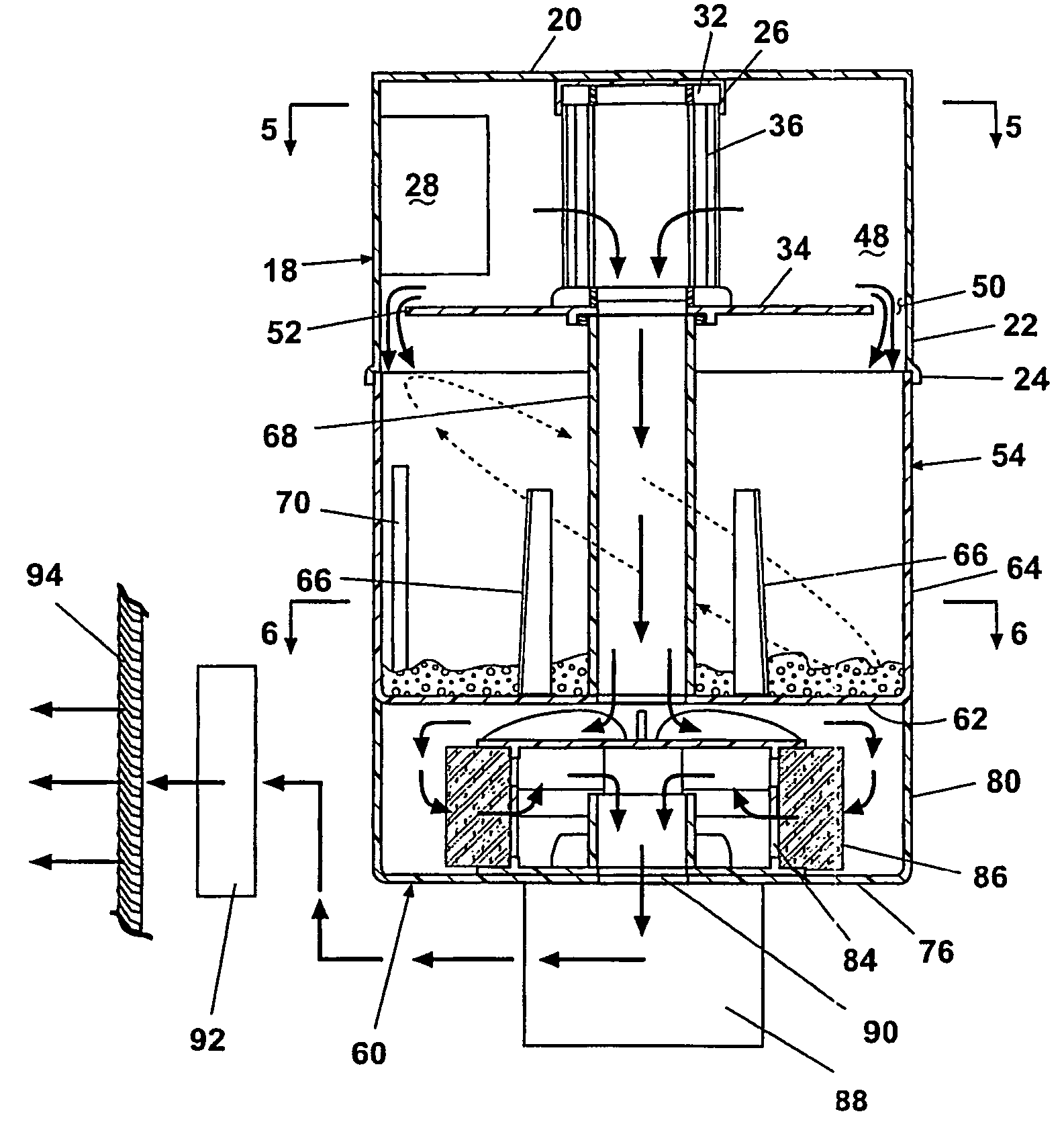
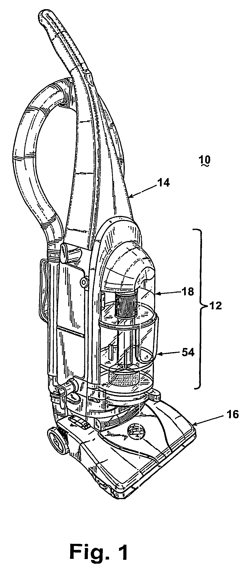
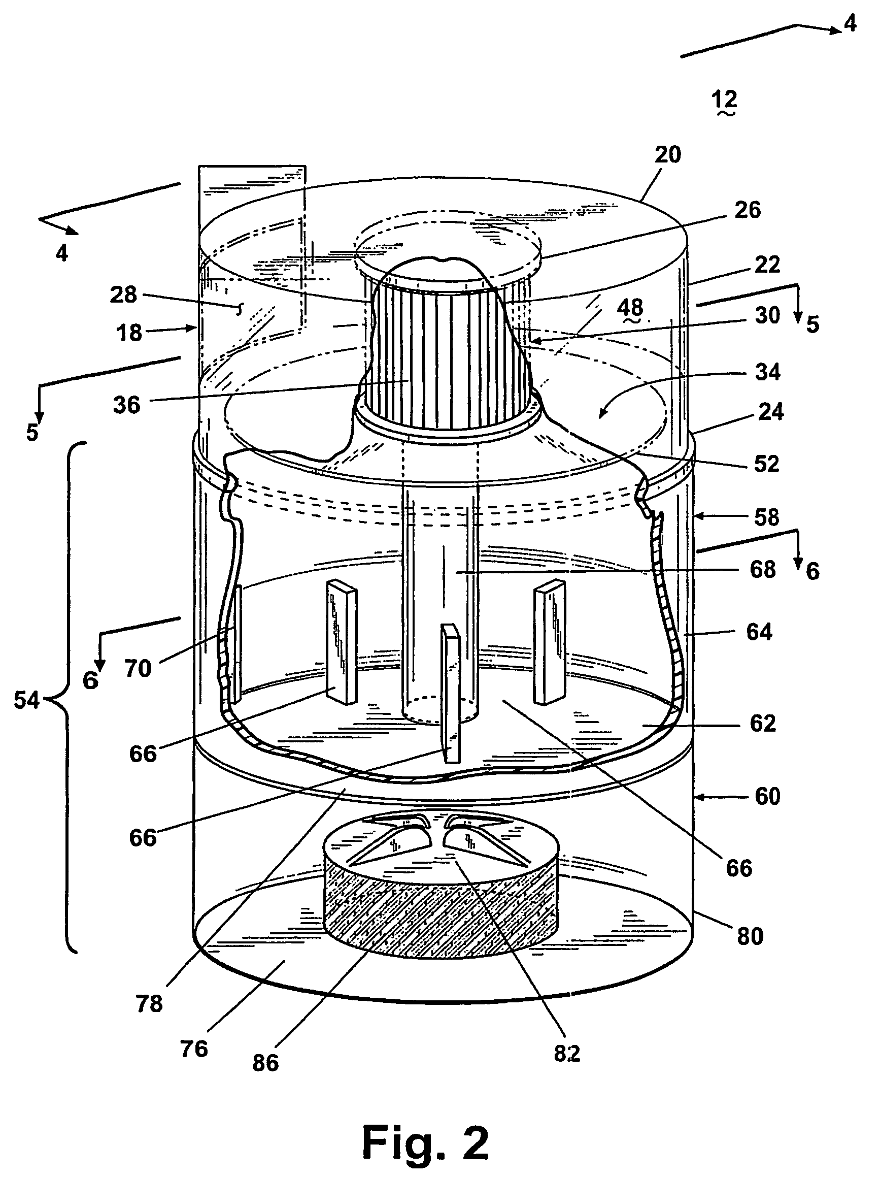
[0024]An upright vacuum cleaner 10 with cyclonic dirt separator and dirt cup assembly 12 according to the invention is shown in FIG. 1, comprising an upright handle 14 pivotally mounted to a nozzle base 16. The upright handle 14 mounts the cyclonic dirt separator and dirt cup assembly 12 according to the invention. The nozzle base has a conventional suction opening beneath a forward portion of the base. Referring to FIG. 2, the cyclonic dirt separator and dirt cup assembly 12 comprises a cylindrical cyclone separator 18 having an upper wall 20 and a sidewall 22, the sidewall 22 terminating in a lower offset lip 24. An annular collar 26 depends from the upper wall 20, the collar 26 and is centered in the cylindrical cyclone separator 18. The sidewall 22 further includes a tangential air inlet 28 aligned proximate the upper wall 20 for generating a tangential airflow in the separator 18 parallel to the upper wall 20 and forms an inlet opening in a cyclonic airflow chamber formed by th...


PUM

PropertyMeasurementUnit
anglesaaaaaaaaaa
anglesaaaaaaaaaa
angleaaaaaaaaaa

Abstract

A vacuum cleaner with cyclonic dirt separation and a bottom discharge dirt cup beneath the cyclone separator and a filter beneath the dirt cup and between the dirt cup and a suction motor inlet. A separator plate separates the cyclone separator from the dirt cup. Fins project from a sidewall of the dirt cup, and fingers projecting from a bottom wall of the dirt cup. A hollow standpipe in the dirt cup transports working air from the cyclone separator outlet to the filter.

Description

CROSS-REFERENCE TO RELATED APPLICATIONS[0001]This application claims priority on International Application No. PCT / US2004 / 034841, filed Oct. 21, 2004, which claims the benefit of U.S. Provisional Patent Application 60 / 481,542, filed Oct. 22, 2003, both are incorporated herein in their entirety.BACKGROUND OF THE INVENTION[0002]1. Field of the Invention[0003]The invention relates to suction cleaners, and in particular to a separator for a suction cleaner. In one of its aspects, the invention relates to a separator with a cyclonic airflow path to separate dirt and debris from air drawn into the cleaner. In another of its aspects, the invention relates to a separator that deposits the dirt and debris in a collection receptacle. In another of its aspects, the invention relates to a bottom discharge dirt-collecting bin with an integrated filter chamber. In another of its aspects, the invention relates to a separator including structure for inhibiting the re-entrainment of debris that vaci...

Claims


Application Information

Patent Timeline
Patent Type & Authority Patents(United States)
IPC IPC(8): B01D45/12A47L9/12A47L9/16
CPCA47L9/127A47L9/1608B01D45/16A47L9/1683A47L9/1666Y10S55/03A47L9/16B04C5/185B04C5/187
Inventor FESTER, JOSEPH A.
Owner BISSELL INC
Why Eureka
Try Eureka