Compact cyclonic separation device

a cyclonic separation and compact technology, applied in the direction of cleaning filter means, separation processes, auxiliaries, etc., can solve the problem of becoming increasingly difficult to prevent the air flow from progressing down the inside of the separation chamber

Active Publication Date: 2006-03-02
SHARKNINJA OPERATING LLC
View PDF10 Cites 162 Cited by
  • Summary
  • Abstract
  • Description
  • Claims
  • Application Information

AI Technical Summary

Benefits of technology

[0007] Generally speaking, in accordance with the invention, a cyclonic separation attachment for a vacuum cleaner having an elongated compact housing with an inlet opening and an inlet tube with a vane assembly is provided. The housing includes an upper separation potion and a lower dirt collection portion. The vane assembly includes a vertical inlet tube with a vortex vane upstream of the cylindrical housing. A central outlet tube assembly extends into the upper portion of the separation portion of the housing. A decoupling or disrupter ring is located on the inside wall of the housing between the separation portion and the collection portion. An outlet tube disc is suspended from the bottom of the outlet tube and is positioned below the level of disrupter ring. The lower portion of the separation housing collects the dirt and has an openable door for the easy removal of collected dirt.

Problems solved by technology

As the size of the vacuum cleaners becomes smaller and more compact, it becomes increasingly difficult to prevent the air flow from progressing down the inside of the separation chamber from disturbing the dirt collected in the dirt collecting container.

Method used


Image

  • Compact cyclonic separation device
  • Compact cyclonic separation device
  • Compact cyclonic separation device

Examples


Embodiment Construction

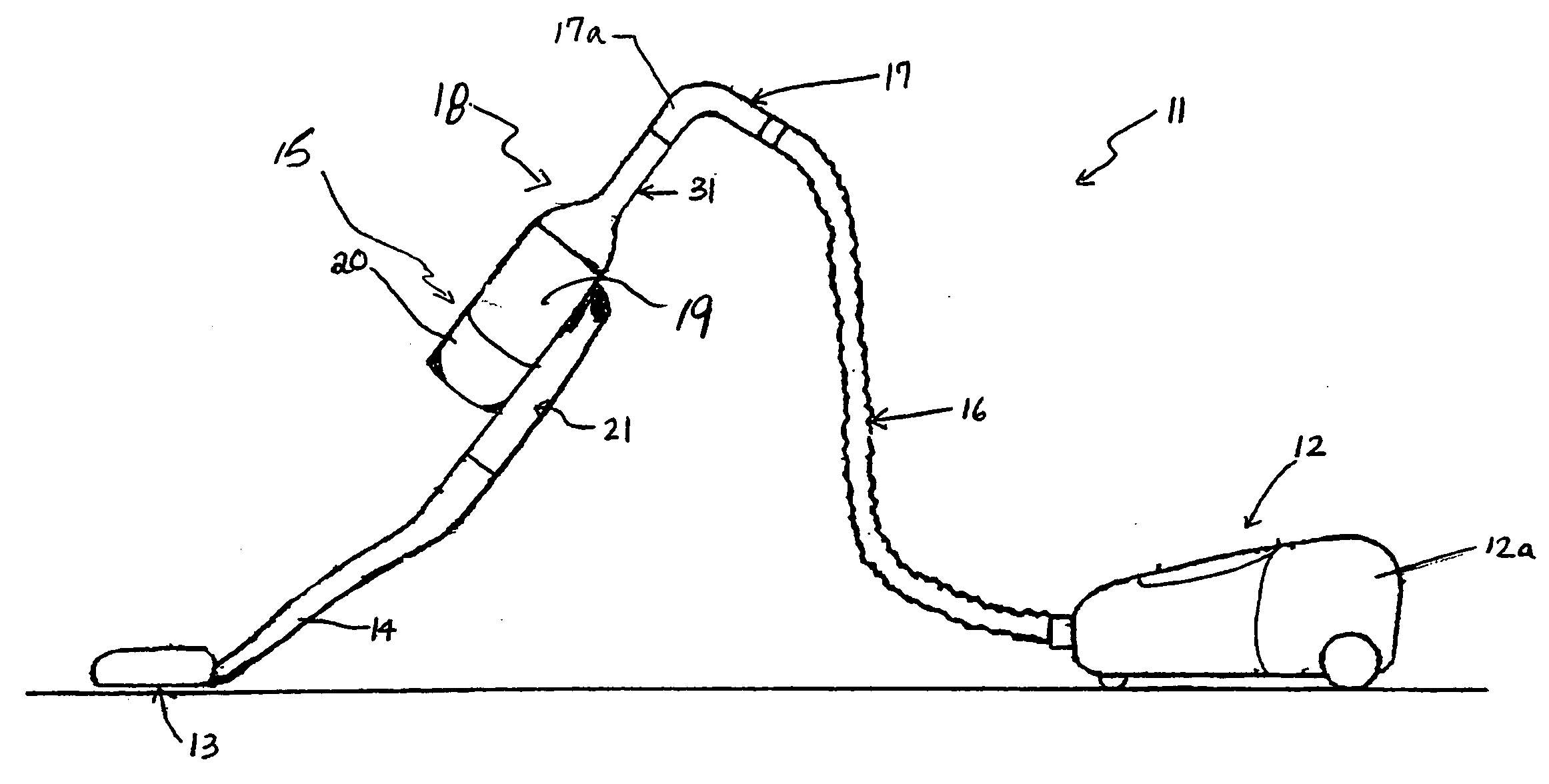
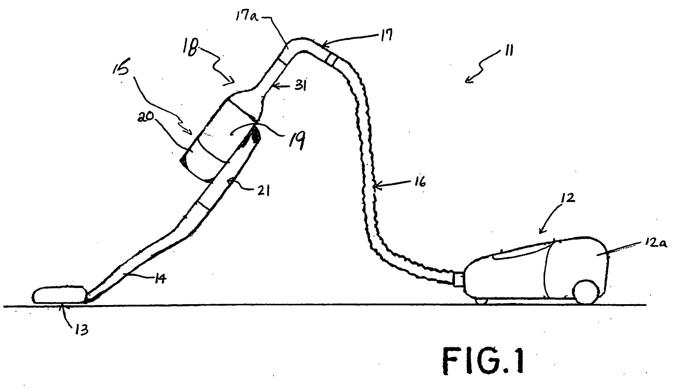
[0023]FIG. 1 illustrates a canister-type vacuum cleaner 11 having a canister housing 12 including a vacuum source 12a. A floor nozzle dirt collector 13 with a suction opening is connected to a rigid vacuum handle 17 that is connected to housing 12 by a flexible hose 16. Vacuum handle 17 has an inlet pipe section 17a. A cyclonic separation device 18, constructed and arranged in accordance with the invention, is mounted between rigid nozzle pipe section 14 and vacuum handle tube section 17a.

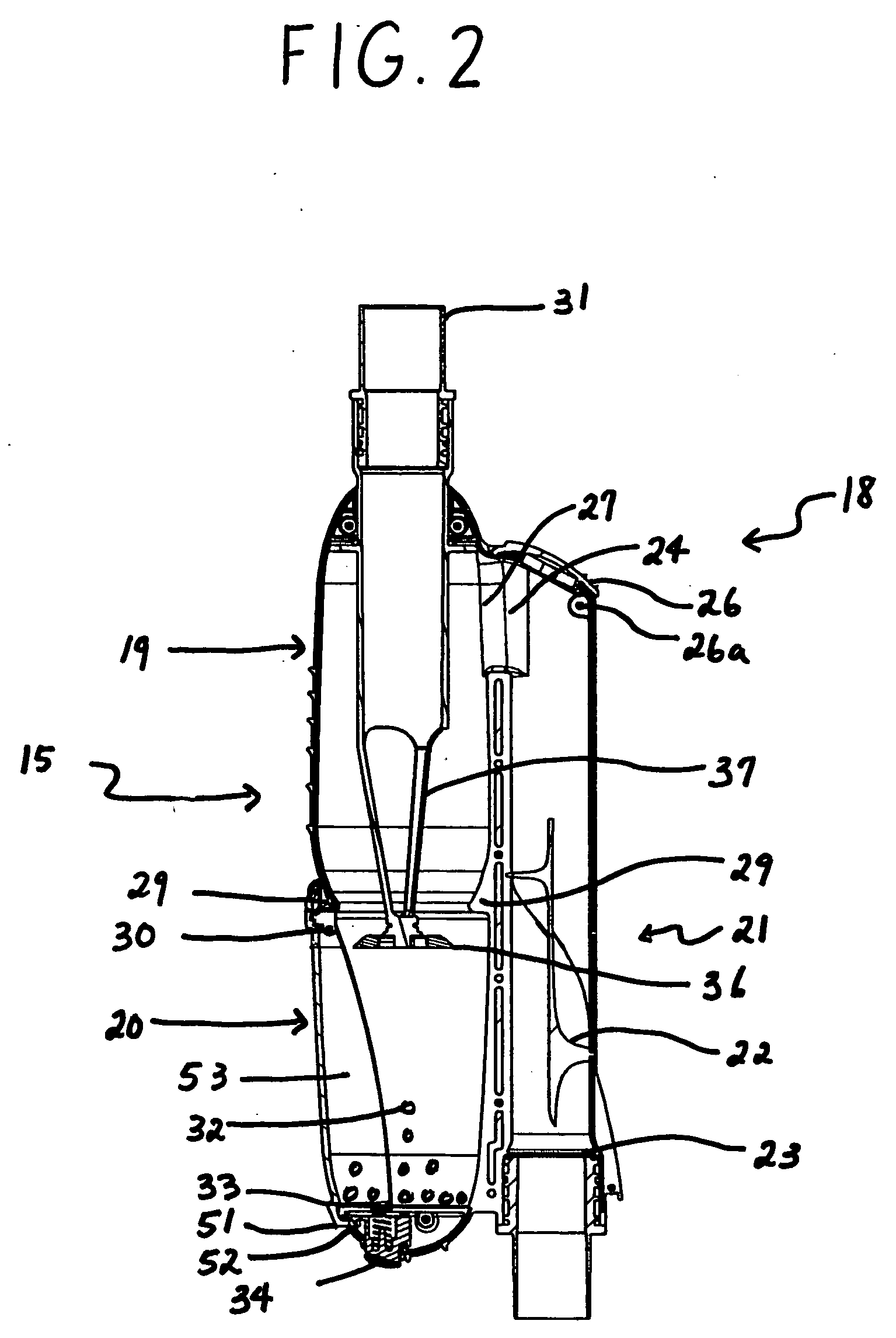
[0024] Cyclonic separation device 18 increases the cleaning efficiency by removing dirt from the inlet air before it reaches the filtering and collection elements in housing 12. Cyclonic separation device 18 includes an elongated substantially cylindrical housing 15 having a central axis with an upper separation portion 19 and a lower collection portion 20. A central exhaust pipe 31 is provided above separation portion 19. Inlet air is fed into housing 15 by an inlet tube 21 mounted adjacent to ho...


PUM

PropertyMeasurementUnit
angleaaaaaaaaaa
angleaaaaaaaaaa
angleaaaaaaaaaa

Abstract

A cyclonic separation device for a vacuum cleaner including a cylindrical housing, an inlet tube parallel to the axis of the housing having a vortex vane disposed axially in the inlet tube. Air rotates in one direction in the inlet tube, and preferably in the opposite direction in the housing. The housing includes a cylindrical sidewall with an upper central outlet tube and a closed bottom for collecting separated dirt. A disrupter ring located on the inside wall of the middle portion of the housing includes a curved surface and sharp edge for lifting air flow off the housing wall. An outlet tube disc spaced from the inlet of the outlet tube is located in the housing below the disrupter ring.

Description

CROSS-REFERENCE TO RELATED APPLICATIONS [0001] This is a continuation-in-part of U.S. application Ser. No. 10 / 926,609, filed Aug. 26, 2004, the entire disclosure of which is hereby incorporated by reference.BACKGROUND OF THE INVENTION [0002] The invention relates to a cyclonic separation device for a vacuum cleaner. More particularly, it relates to a cyclonic separation attachment to be placed on the inlet pipe between the vacuum nozzle and the handle of the inlet pipe to increase the dirt separation and collection of a vacuum cleaner having a rigid inlet pipe. [0003] Cyclonic separating devices for vacuum cleaners have been known for some time. For example, U.S. Pat. No. 6,195,835 to Samsung Kwangju Electronics discloses a vacuum cleaner having a cyclone dust collecting device. Here, the cyclone dust collecting device includes a dirt separating cyclonic chamber with a shroud extending into the chamber having a plurality of holes of a size to prevent the dirt of a predetermined part...

Claims


Application Information

Patent Timeline
Patent Type & Authority Applications(United States)
IPC IPC(8): B01D45/00
CPCA47L9/1608A47L9/1683A47L9/1658A47L9/165B01D45/12Y10S55/03
Inventor ARNOLD, ADRIAN CHRISTOPHERARNOLD, ARTHUR JOHN
Owner SHARKNINJA OPERATING LLC
Why Eureka
Try Eureka