
Loudspeaker including a cone circumscribed by a stiffener

a technology of a loudspeaker and a cone is applied in the direction of loudspeaker diaphragm shape, electrical transducer, transducer details, etc., which can solve the problems of reducing the efficiency of the loudspeaker, the stiffness of the cone, and the limited amount of acoustic energy of the conventional loudspeaker

Active Publication Date: 2010-05-04
COMMUNITY LIGHT & SOUND
View PDF5 Cites 13 Cited by
  • Summary
  • Abstract
  • Description
  • Claims
  • Application Information

AI Technical Summary

Problems solved by technology

Conventional loudspeakers are limited in the amount of acoustic energy that can be produced with acceptably audio low distortion.
The limit arises primarily from the structure of the surround, which limits the excursions of the cone, and the stiffness of the cone, which distorts under large excursions.
Each of the aforementioned patents discloses a method of stiffening a cone which adds considerable mass to the cone, thus lowering the efficiency of the loudspeaker and reducing it's high frequency response.

Method used


Image

  • Loudspeaker including a cone circumscribed by a stiffener
  • Loudspeaker including a cone circumscribed by a stiffener
  • Loudspeaker including a cone circumscribed by a stiffener

Examples


Embodiment Construction

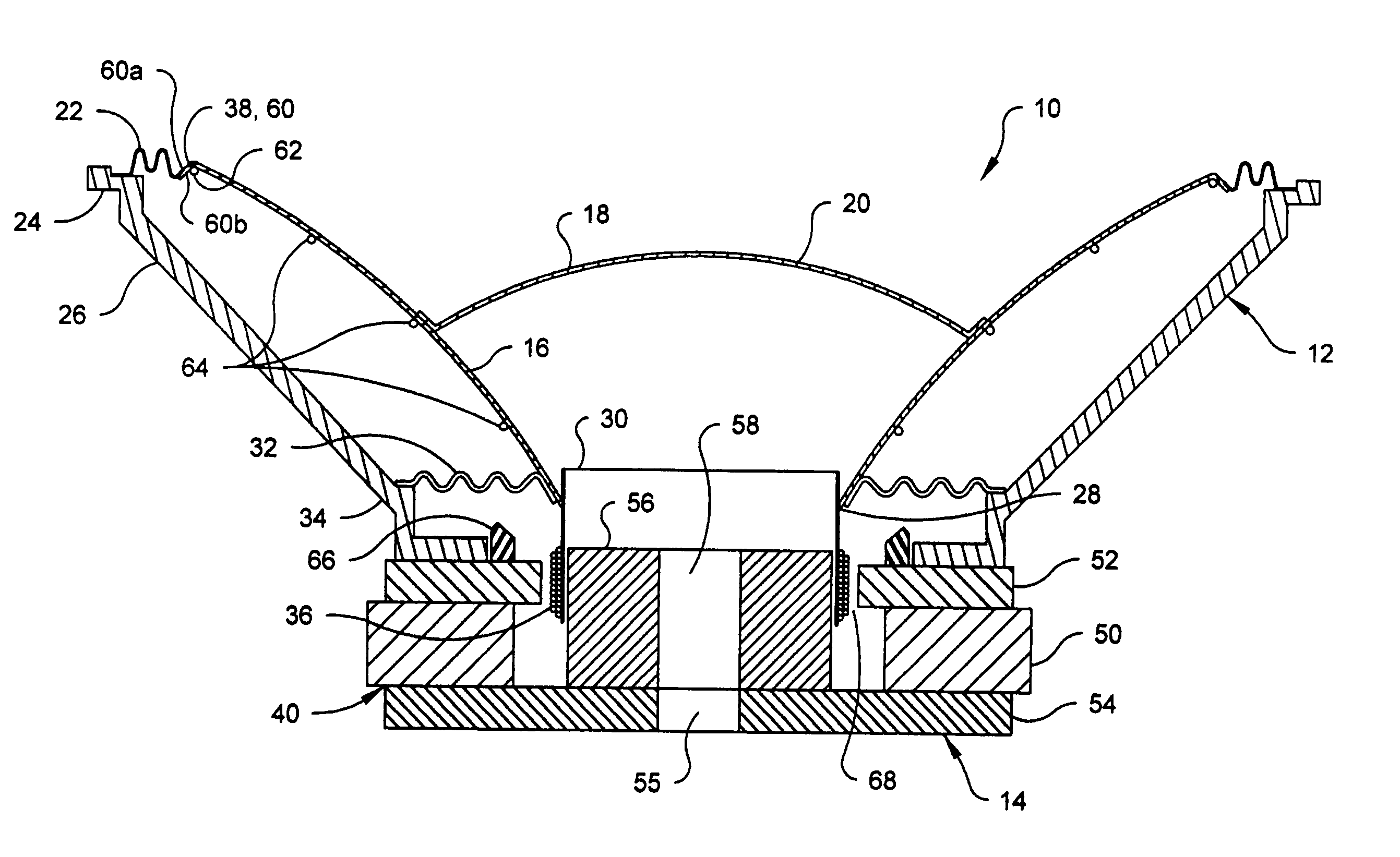
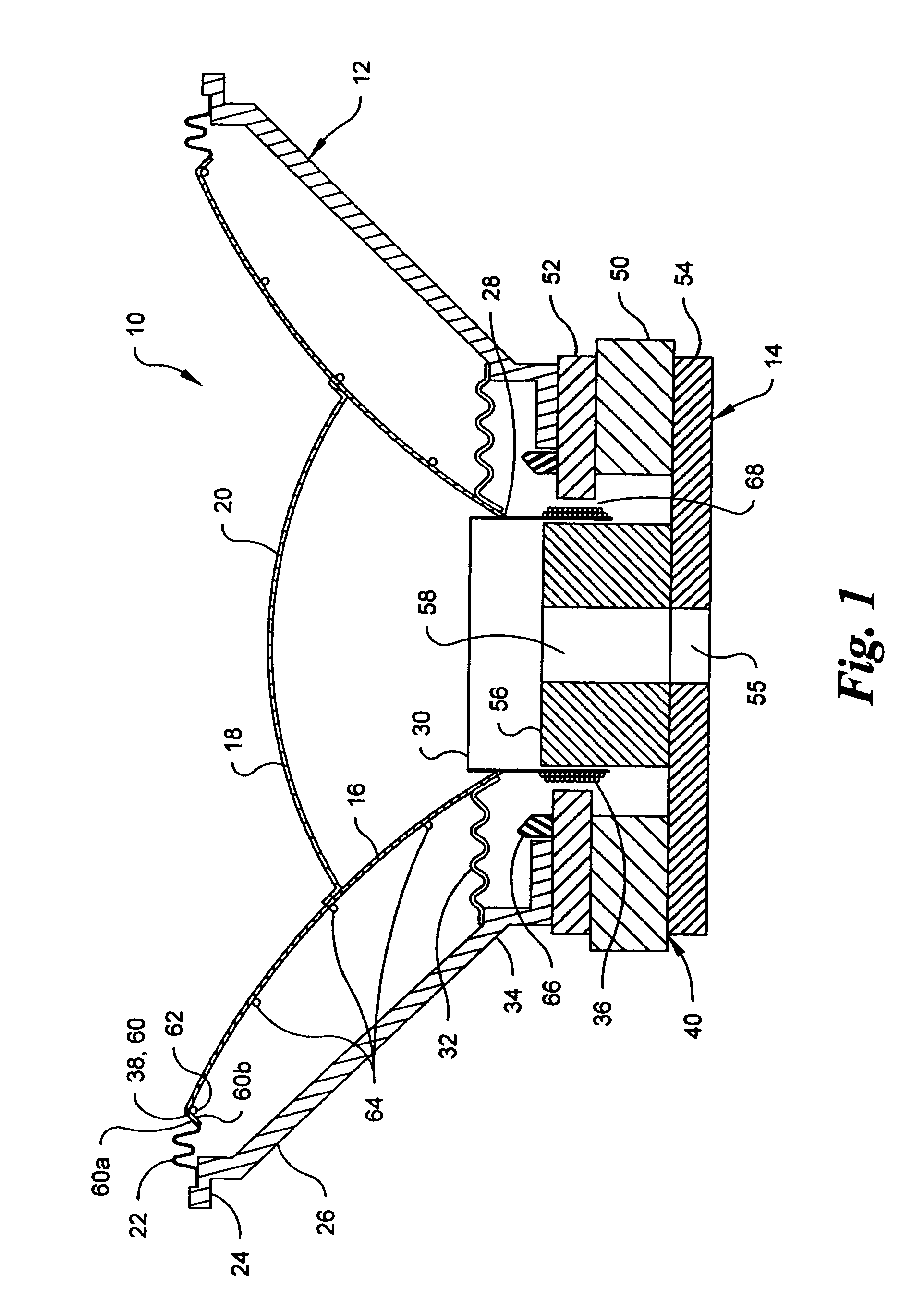
[0021]Referring now to FIG. 1 there is shown in sectional view, a preferred embodiment of a loudspeaker 10 according to the present invention. The loudspeaker 10 comprises a diaphragm assembly 12, and a driver assembly 14 that operates the diaphragm assembly 12 for producing acoustical output.

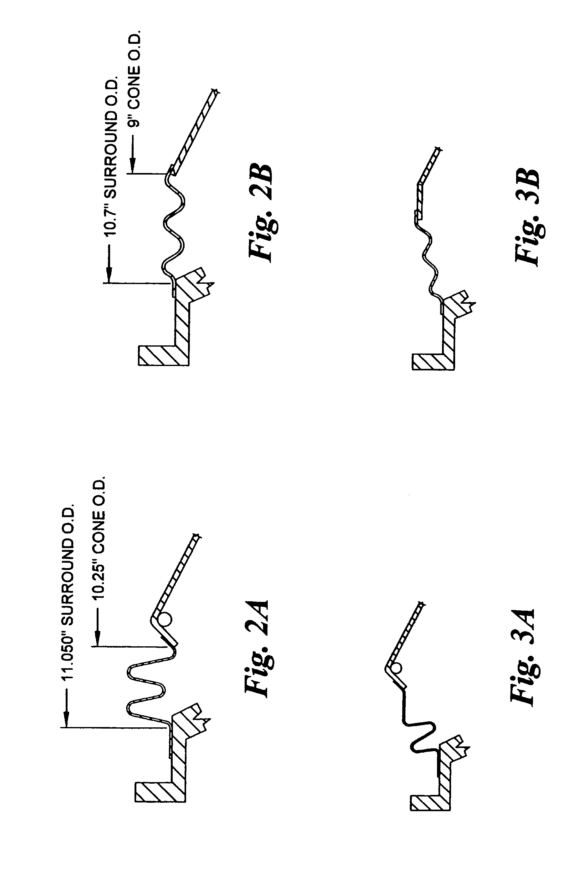
[0022]The diaphragm assembly 12 includes a frame 26, a cone 16 attached with an adhesive or the like to a dome 18 to form a diaphragm 20. An outer edge 38 of the cone 16 is connected to an upper end 24 of the frame 26 by a surround 22. A lower end 28 of the cone 16 is connected to a voice coil former 30 which forms part of the driver assembly 14. The voice coil former 30 (hereafter former) is in turn connected to the frame 26 through a flexible spider 32 that extends between the former 30 and a lower end 34 of the frame 26. With the arrangement of the surround 22 and the spider 32, the diaphragm 20 is free to move in an axial direction but is restrained from movement in a radial direction with ...


PUM


Abstract

The present invention is a loudspeaker. The loudspeaker includes a frame, a cone having an outer edge in a shape of a reverse angle flange, and a reinforcing ring bonded to a back side of the flange.

Description

CROSS-REFERENCE TO RELATED APPLICATIONS[0001]This application claims the benefit of Provisional Application No. 60 / 672,378 entitled Carbon Ring Cone, filed Apr. 18, 2005, the contents of which are incorporated herein, be reference, in their entirety.BACKGROUND OF THE INVENTION[0002]A loudspeaker for audio signals converts electrical energy into mechanical energy by vibrating a diaphragm. The vibrating diaphragm causes motion of the surrounding air, thus producing acoustic energy.[0003]The most common form of diaphragm for low frequency and midrange loudspeakers is a cone. A voice coil immersed in a magnetic field is attached to the neck of the cone, and the cone is attached to a rigid frame by means of flexible members at both the neck and the outer edge of the cone. These flexible members (i.e. a “spider” at the neck, and a “surround” at the outer edge) allow the cone to move fore and aft within the frame while maintaining axial alignment (i.e. preventing the cone from tilting or r...

Claims


Application Information

Patent Timeline
Patent Type & Authority Patents(United States)
IPC IPC(8): H04R25/00
CPCH04R7/20H04R9/041H04R2307/207H04R2307/204H04R9/06
Inventor HOWZE, BRUCE W.
Owner COMMUNITY LIGHT & SOUND
Learn More