Single patient, personal use air mattress having a single perimeter seam

a technology of air mattress and perimeter seam, which is applied in the field of patient transfer devices, can solve the problems that none of the foregoing prior art transfer mattresses are appropria

Inactive Publication Date: 2010-05-11
D T DAVIS ENTERPRISES LTD D B A HOVERTECH INT
View PDF19 Cites 32 Cited by
  • Summary
  • Abstract
  • Description
  • Claims
  • Application Information

AI Technical Summary

Problems solved by technology

None of the foregoing prior art transfer mattresses are appropriate for assuring single use by and personal to a single patient since all are susceptible to some cleaning that would mask the fact that there had been a prior use with the same or different patient.

Method used


Image

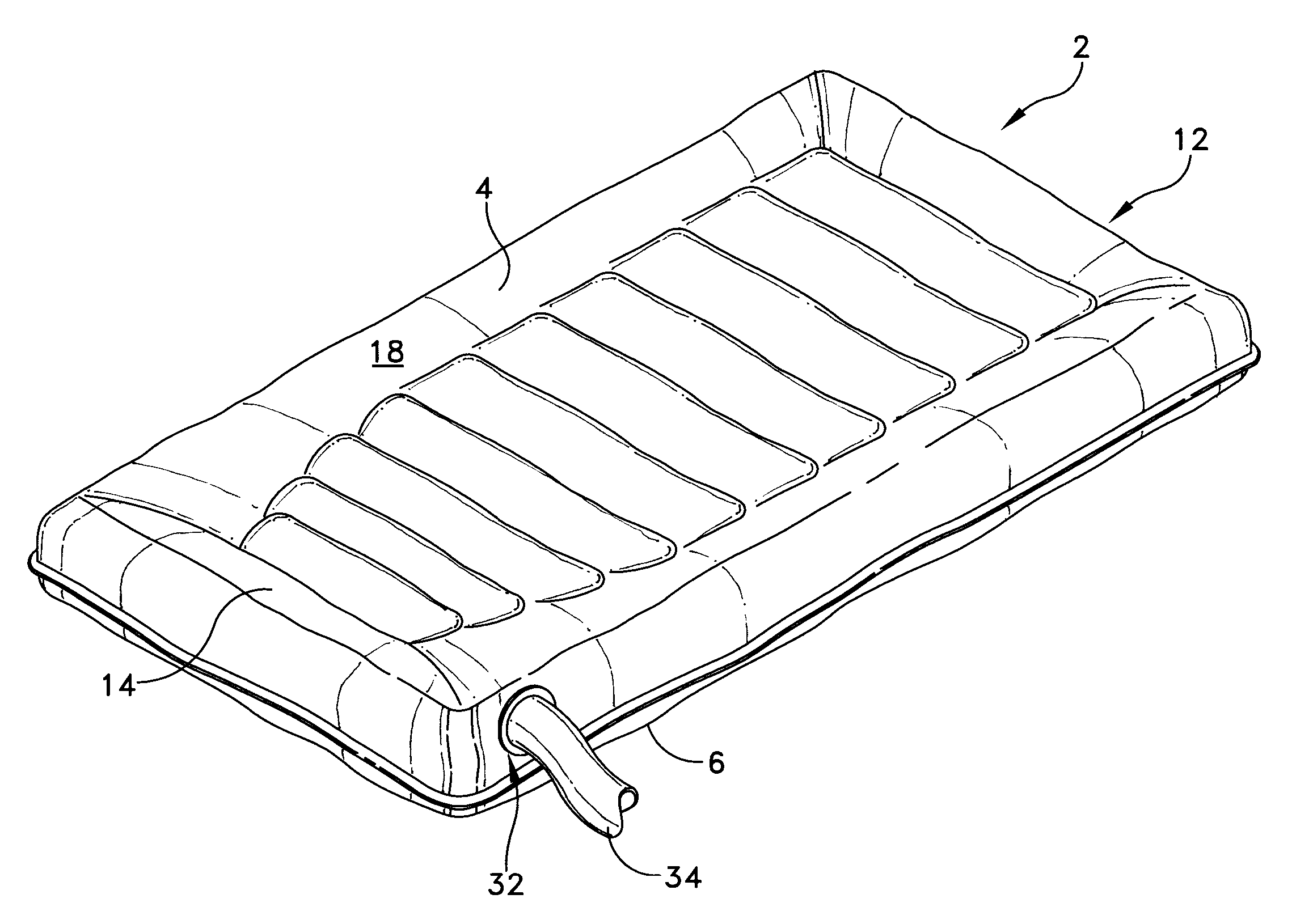
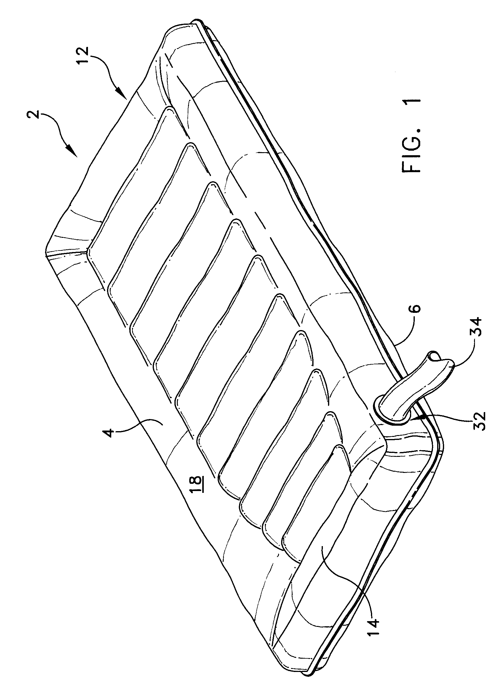
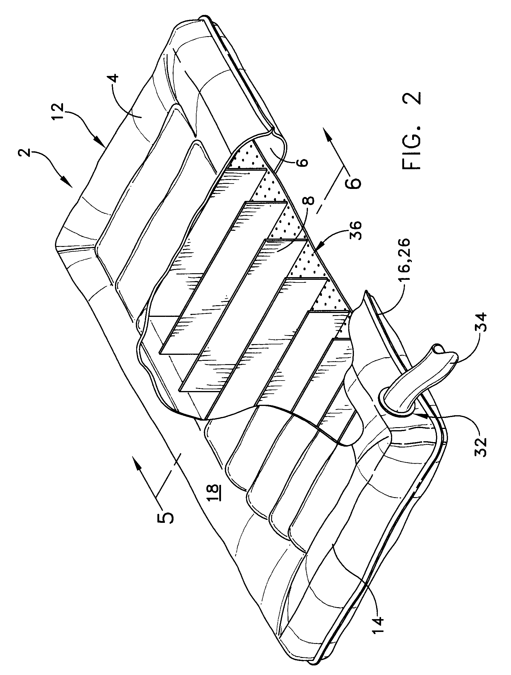
  • Single patient, personal use air mattress having a single perimeter seam
  • Single patient, personal use air mattress having a single perimeter seam
  • Single patient, personal use air mattress having a single perimeter seam

Examples


Embodiment Construction

[0017]This description of preferred embodiments is intended to be read in connection with the accompanying drawings, which are to be considered part of the entire written description of this invention. The drawing figures are not necessarily to scale and certain features of the invention may be shown exaggerated in scale or in somewhat schematic form in the interest of clarity and conciseness. In the description, relative terms such as “horizontal,”“vertical,”“up,”“down,”“top” and “bottom” as well as derivatives thereof (e.g., “horizontally,”“downwardly,”“upwardly,” etc.) should be construed to refer to the orientation as then described or as shown in the drawing figure under discussion. These relative terms are for convenience of description and normally are not intended to require a particular orientation. Terms including “inwardly” versus “outwardly,”“longitudinal” versus “lateral” and the like are to be interpreted relative to one another or relative to an axis of elongation, or...


PUM


Abstract

A single patient, personal use patient transfer mattress is provided including at least a substantially permanently stainable top sheet having a width, a length, and longitudinally oriented peripheral edges and a bottom sheet having the same width, the same length, longitudinally oriented peripheral edges and a plurality of perforations. The longitudinally oriented peripheral edges of the top and bottom sheets are sealingly fastened to one another. A plurality of baffles, each having a width and a length, are attached to an inner surface of the top sheet and an inner surface of the bottom sheet so as to be transversely oriented between the top sheet and the bottom. The baffles along with the widths of the top and bottom sheets define a radially-outwardly curved perimeter wall that is disposed between an edge of the baffles and the sealed peripheral edges of the top and bottom sheets. The radially-outwardly curved perimeter wall has a width y that is determined by the following relationship:d⁢⁢π-x2≤ywhere d comprises a height of the longitudinally extensive pontoon and x comprises the width of the baffles.

Description

[0001]This application is a continuation-in-part of, and claims priority from application Ser. No. 10 / 998,768, filed Nov. 29, 2004, which itself is a continuation application of U.S. application Ser. No. 10 / 638,450, filed on Aug. 11, 2003. and now issued as U.S. Pat. No. 6,898,809.FIELD OF THE INVENTION[0002]The present invention generally relates to patient transfer devices and, more particularly to a patient transfer apparatus which employs an air bearing to facilitate the transfer.BACKGROUND OF THE INVENTION[0003]Patient handling mattresses are known in the art which include at least two flexible material sheets, that together define a plenum chamber, with at least one sheet being perforated with small pinholes over at least a central surface area, and which open up directly to the interior of the plenum chamber. Such prior art mattresses are used by arranging the perforated sheet so that it faces an underlying fixed, generally planar support surface, such as a floor or table. Wh...

Claims


Application Information

Patent Timeline
Patent Type & Authority Patents(United States)
IPC IPC(8): A47C27/08
CPCA61G1/013A61G7/1028A61G7/1026A61G7/05769A61G7/1021
Inventor DAVIS, DAVID T.
Owner D T DAVIS ENTERPRISES LTD D B A HOVERTECH INT
Why Eureka
Try Eureka