Multi-metering and diffusion transpiration cooled airfoil

a technology of transpiration and airfoil, which is applied in the direction of liquid fuel engines, machines/engines, mechanical equipment, etc., can solve the problems of reducing the efficiency of the turbine and increasing the temperature of the coating surface, so as to improve the performance of the turbine stage, improve the durability of the coating layer, and improve the effect of high temperature resistan

Inactive Publication Date: 2010-05-18
FLORIDA TURBINE TECH
View PDF15 Cites 27 Cited by
  • Summary
  • Abstract
  • Description
  • Claims
  • Application Information

AI Technical Summary

Benefits of technology

[0010]The present invention is a turbine airfoil with a new spar airfoil cooling construction that utilizes a multi-metering diffusion compartmental cooling apparatus in conjunction with a transpiration cooling process and a thermal sprayed refractory protective coating to achieve a cooled wall for the external protective coating layer. The airfoil wall includes a plurality of diffusion chambers opening onto the outer wall surface and having cooling air supply passages opening onto the back surface. A ceramic material core having the shape of fine cooling

Problems solved by technology

As the turbine inlet temperature increases, the cooling flow demand for cooling the airfoil will increase and thus reduce the turbine effic

Method used


Image

  • Multi-metering and diffusion transpiration cooled airfoil
  • Multi-metering and diffusion transpiration cooled airfoil
  • Multi-metering and diffusion transpiration cooled airfoil

Examples


Embodiment Construction

[0015]The present invention is a turbine airfoil, such as a stator vane or a rotor blade, used in a gas turbine engine in which the airfoil requires film cooling and a high temperature resistant coating to protect the airfoil from the high temperature gas flow. However, the invention is not limited to turbine airfoils. The invention could apply to any substrate material that uses a high temperature resistant coating to provide additional protection to the metal substrate. For example, the combustor liner of a gas turbine engine could also use this invention. Also, other high temperature resistant substrates that are used in an apparatus other than a gas turbine engine.

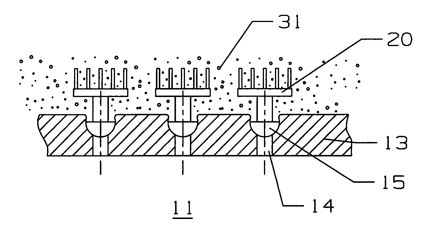
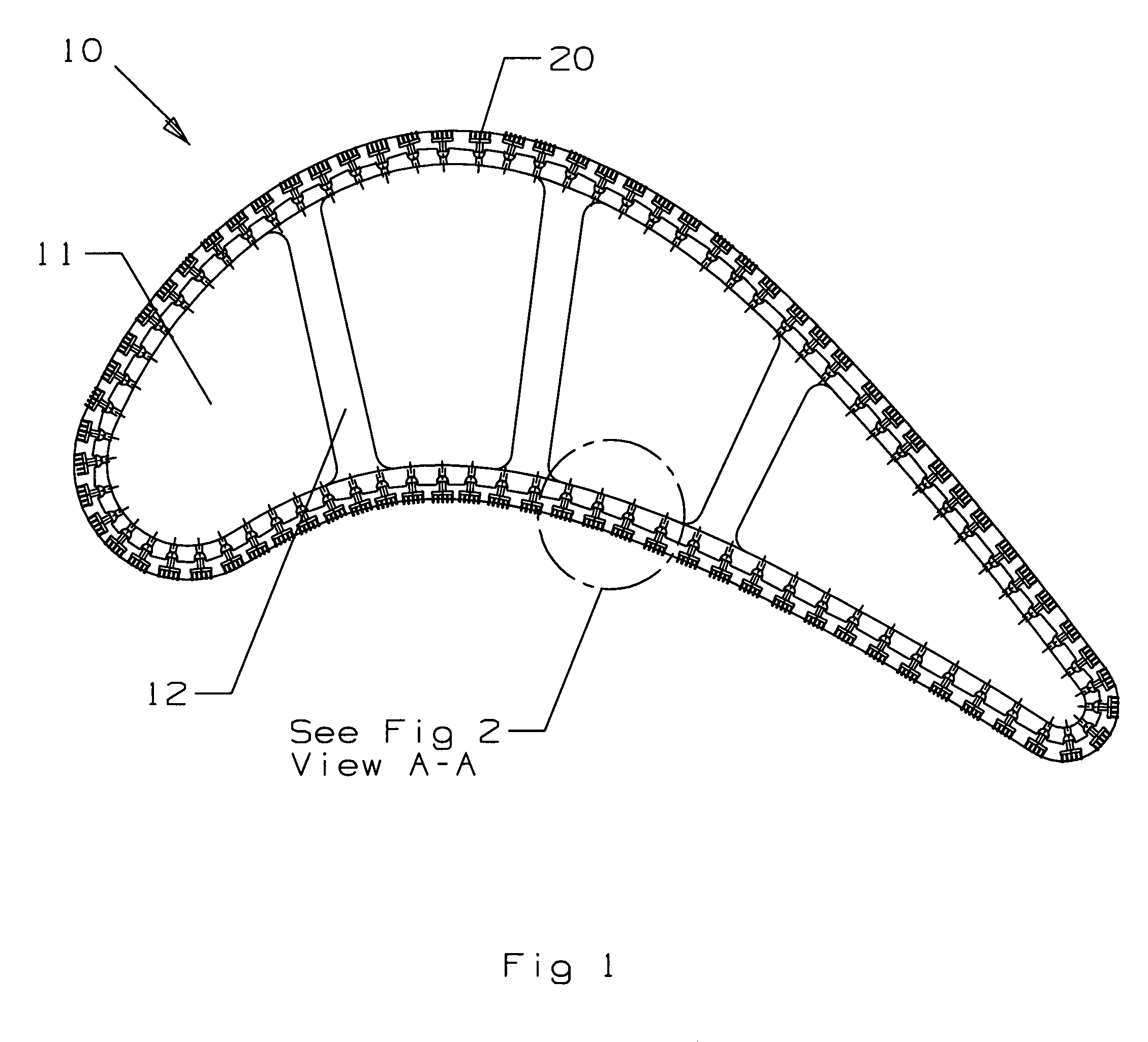
[0016]The airfoil 10 of the present invention is shown in FIG. 1 in which a plurality of cooling supply compartments or channels 11 are formed by the airfoil walls and ribs 12 extending from the pressure side wall to the suction side wall. Four compartments 11 are shown in FIG. 1. However, more or less than four compar...


PUM

PropertyMeasurementUnit
Diameteraaaaaaaaaa
Diameteraaaaaaaaaa
Temperatureaaaaaaaaaa

Abstract

A turbine airfoil, or a substrate exposed to a high temperature environment, having a plurality of individual cooling circuits in the airfoil wall, each individual cooling circuit having a first metering hole connecting the cooling circuit to a cooling air supply, a first diffusion cavity, a second metering hole, and a plurality of fine film cooling holes connected between the second diffusion cavity and the surface of a high temperature resistant coating. The coating is a refractory coating to provide higher heat resistance than a ceramic based thermal barrier coating. A process of forming the individual cooling circuits is also disclosed, where a ceramic core representing the above described cooling passages is secured in a “fish bowl” shaped cavity in the substrate wall, the refractory coating is applied to just under the core fingers, and the ceramic core is leached out to leave behind the cooling circuit. The cooling circuit thus formed includes a first metering hole, a first diffusion cavity, a second metering hole, a second diffusion cavity, and a plurality of micro film cooling holes to provide transpiration cooling to the coating surface.

Description

BACKGROUND OF THE INVENTION[0001]1. Field of the Invention[0002]The present invention relates generally to fluid reaction surfaces, and more specifically to a turbine airfoil with film cooling holes.[0003]2. Description of the Related Art Including Information Disclosed Under 37 CFR 1.97 and 1.98[0004]A gas turbine engine includes a turbine section that has a plurality of stages of stator vanes and rotor blades reacting to a high temperature gas flow passing through the turbine to convert the chemical energy from combustion into mechanical energy by rotating the turbine shaft. The efficiency of the turbine, and therefore of the engine, can be increased by increasing the hot gas flow that enters the turbine.[0005]To allow for higher turbine entrance temperatures, the upper stage vanes and blades are made from exotic nickel alloys that can withstand very high temperatures and have complex internal cooling air passages to provide cooling to these airfoils. A thermal barrier coating (TB...

Claims


Application Information

Patent Timeline
IPC IPC(8): F04D29/58
CPCF01D5/183F05D2260/202F05D2300/611F05D2230/90
Inventor LIANG, GEORGE
Owner FLORIDA TURBINE TECH
Why Eureka
Try Eureka