

Buck-boost switching regulator
a switching regulator and buck-boost technology, applied in the direction of automatic control, process and machine control, instruments, etc., can solve the problems of buck-boost operation difficulty, need a more complex pwm modulator, and conventional average current mode devices suffer from various implementation challenges, so as to achieve superior efficiency, reduce ripple current value, and improve light load efficiency
- Summary
- Abstract
- Description
- Claims
- Application Information
AI Technical Summary
Benefits of technology
Problems solved by technology
Method used
Image

Examples
Embodiment Construction
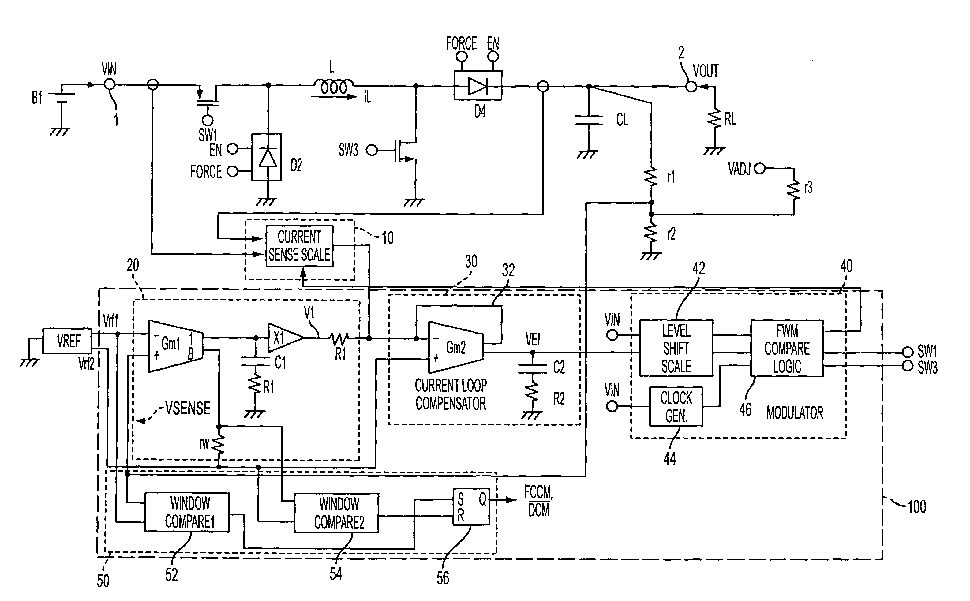
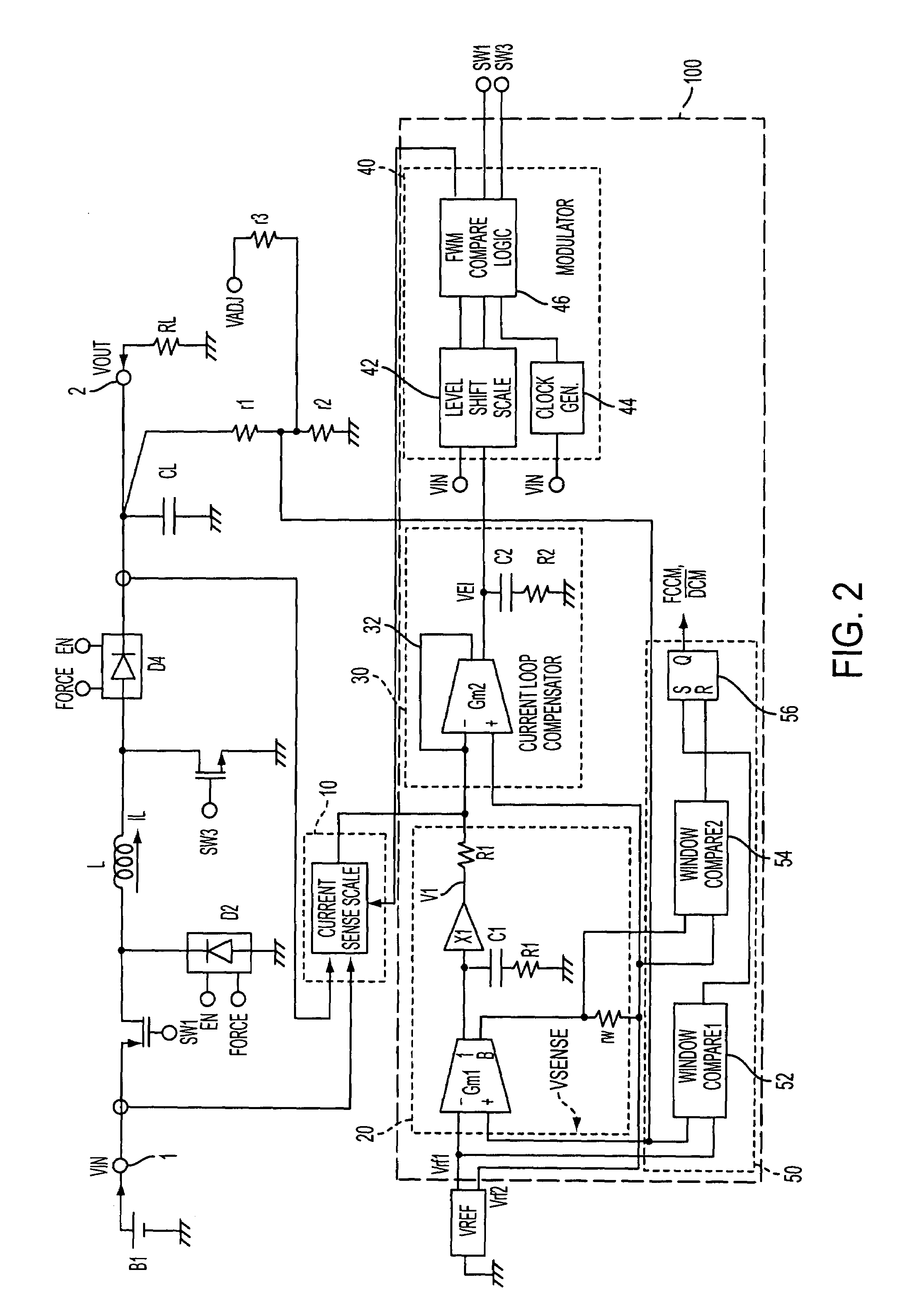
[0024]An exemplary configuration of the switching regulator in accordance with the present invention is shown in FIG. 2. The switching regulator in the given embodiment utilizes average current control mode and employs an input voltage (VIN) feed-forward configuration for good supply voltage rejection. The switching regulator also operates at fixed switching frequency in both continuous and discontinuous inductor current modes (CCM and DCM, respectively), and is capable of both sourcing and sinking current in the output capacitor and load for fast output voltage programming and load change transient response. All current sensing and frequency response determining components as well as the switches and diodes may be integrated in an IC to save space and cost.
[0025]As noted above, average current mode operation is utilized in the present invention. The inductor current IL is measured, its value is time averaged and the averaged current is used for controlling the switches of the switc...
PUM
 Abstract
Description
Claims
Application Information