Display mount

a technology for mounting systems and displays, applied in television systems, electrical apparatus casings/cabinets/drawers, instruments, etc., can solve the problems of entertainment centers occupying significant floor space, limited display options for such devices, etc., and achieve the effect of improving viewing of displays

Inactive Publication Date: 2010-06-15
PEERLESS INDS
View PDF52 Cites 30 Cited by
  • Summary
  • Abstract
  • Description
  • Claims
  • Application Information

AI Technical Summary

Benefits of technology

[0006]Various embodiments comprise systems for mounting multiple display devices, including multiple LCD and plasma flat panel displays. The present mounting systems are particularly well suited to mounting a plurality of display devices from a ceiling or other overhead surface such as where a wall or similar surface may not be near or practical for mounting the displays. The mounting system is configured to mount multiple displays in a display plane that maintains the vertical alignment of the attached displays such that the displays are positioned at the same height and the orientation. The present mounting system may also be used for mounting displays to a wall or other horizontal surface. The mounting systems are further selectively adjustable to provide a desired tilt angle for the attached display devices to enhance viewing of the displays when mounted overhead.

Problems solved by technology

Because conventional “tube” televisions have a relatively large depth, the display options for such devices are quite limited.
Such stands or entertainment centers can take up significant floor space, which is often undesirable.

Method used


Image

  • Display mount
  • Display mount
  • Display mount

Examples


Embodiment Construction

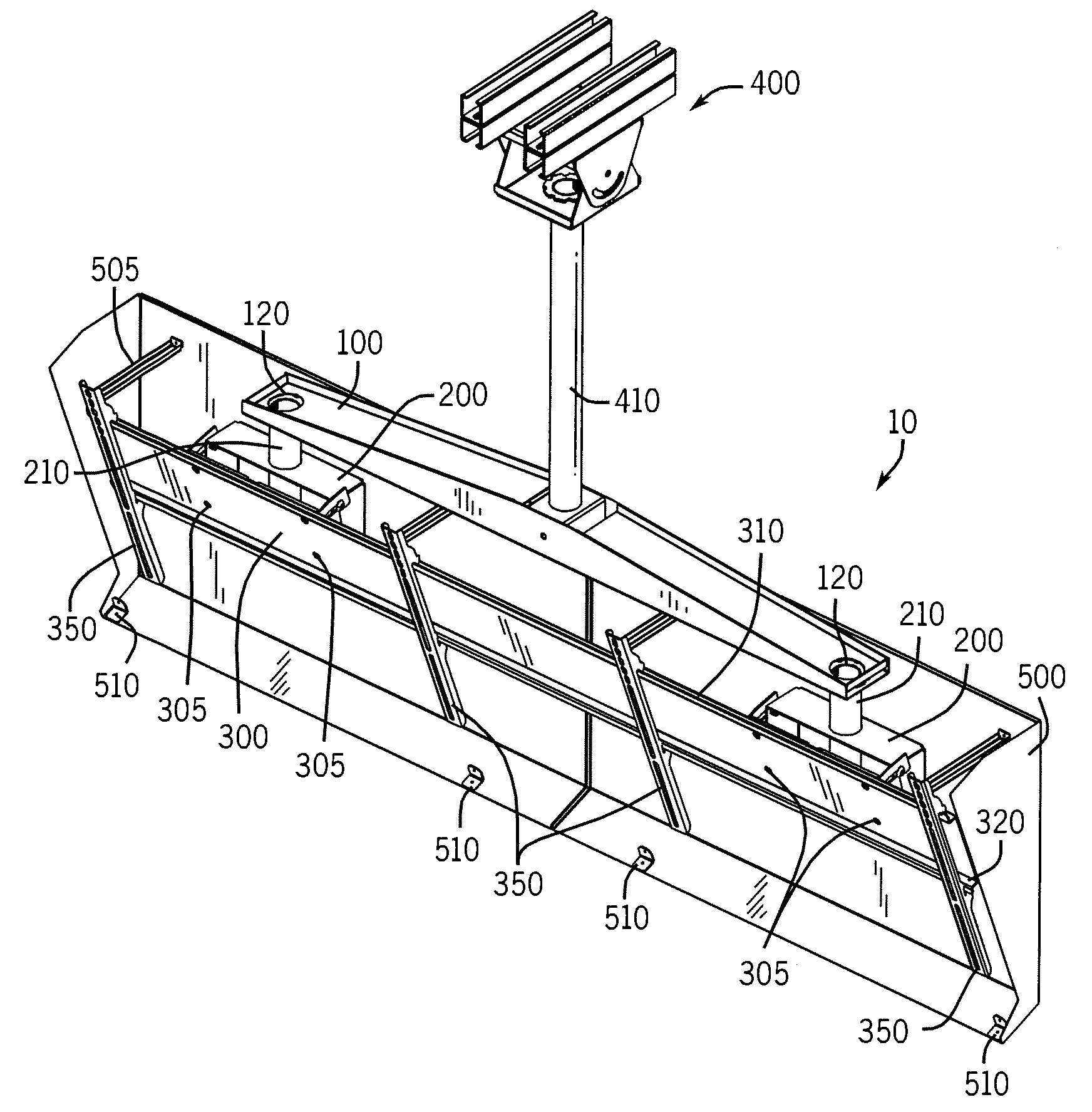
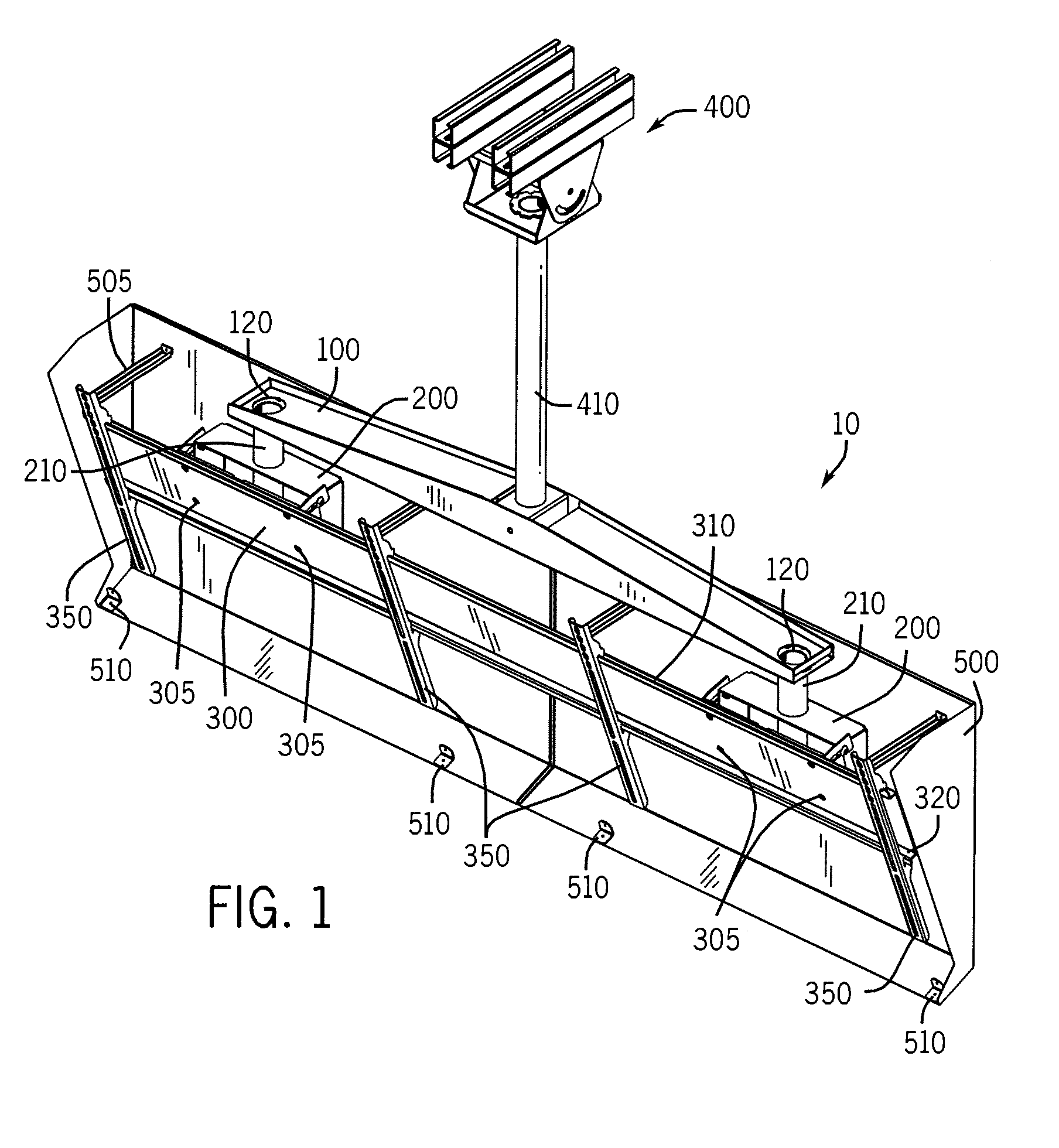
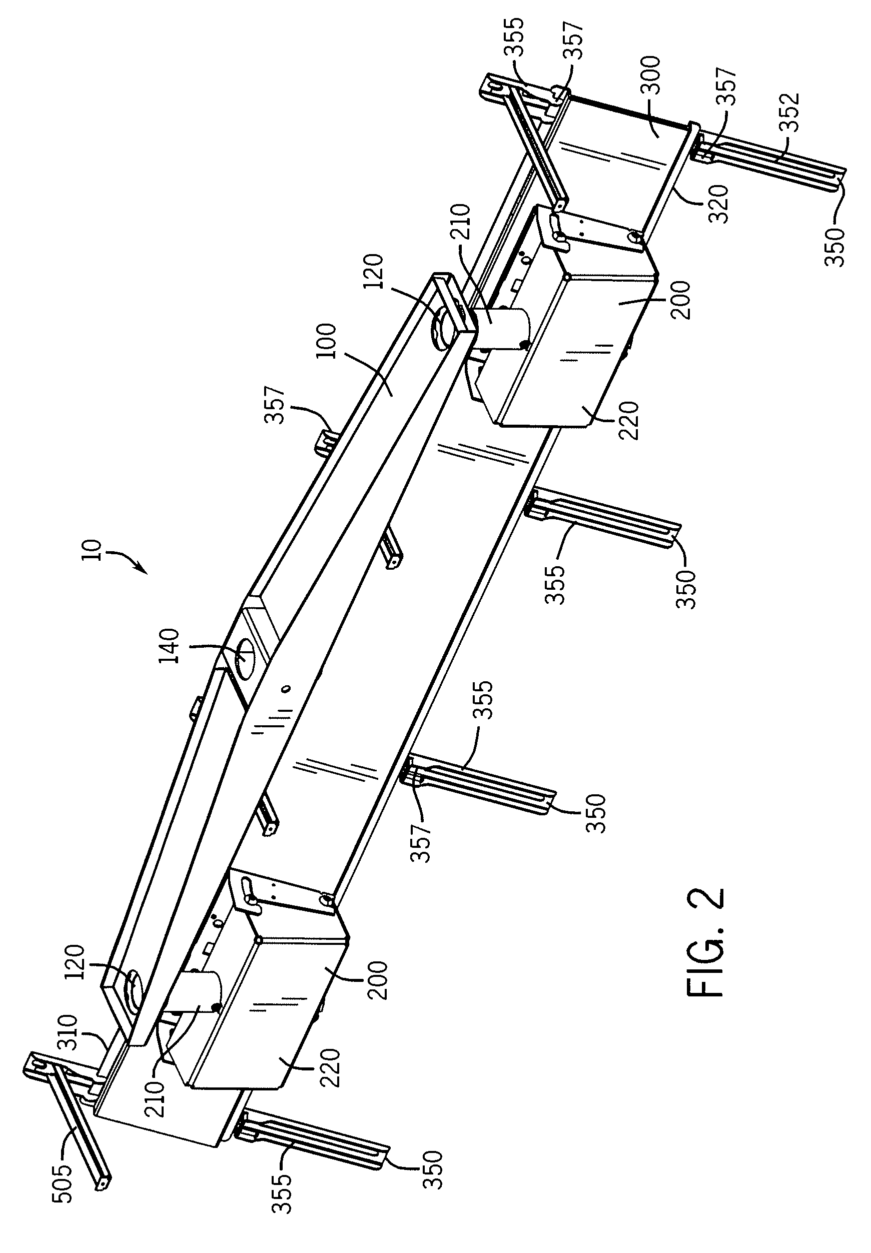
[0016]FIGS. 1-7 illustrates a mounting system 10 constructed in accordance with an embodiment of the present invention. The mounting system 10 comprises a support arm 100 operatively coupled to a device mount assembly 200. The device mount assembly 200 is configured to operatively attach to a device such as a display device 20. A plurality of the device mount assemblies 200 may be operatively coupled to the support arm 100, with each device mount assembly 200 capable of supporting one or more displays. The mounting system 10 further comprises a device support member 300 operatively coupled to the device mount assemblies 200. The device support member 300 may be configured to operatively attach to one or more display devices. A plurality of device brackets 350 may be operatively coupled to the device support member 300 to facilitate attachment of the display devices 20. The mounting system 10 may further comprise a surface mount assembly 400 configured to operatively attach to a moun...


PUM


Abstract

A mounting system for mounting a plurality of devices to a surface, including an overhead surface. According to various embodiments, a support arm is configured to operatively attach to a mounting surface and is operatively connected to a plurality of device support assemblies that include a mount bracket a selectively moveable tilt bracket. A device support member is operatively coupled to the tilt brackets and configured to operatively attach to at least one display device such as a flat panel display. The device support member, and attached devices, are selectively tiltable to a tilt angle.

Description

FIELD OF THE INVENTION[0001]The present invention relates generally to mounting systems for devices. More particularly, the present invention relates to mounting systems for mounting multiple flat-panel displays and similar devicesBACKGROUND OF THE INVENTION[0002]This section is intended to provide a background or context to the invention that is recited in the claims. The description herein may include concepts that could be pursued, but are not necessarily ones that have been previously conceived or pursued. Therefore, unless otherwise indicated herein, what is described in this section is not prior art to the description and claims in this application and is not admitted to be prior art by inclusion in this section.[0003]In recent years, flat panel televisions have become enormously popular in both commercial and residential sectors. As the prices for plasma and liquid crystal display (LCD) flat panel displays have continued to fall, and the quality for the same devices have impr...

Claims


Application Information

Patent Timeline
Patent Type & Authority Patents(United States)
IPC IPC(8): G06F1/16H05K5/00H05K7/00
CPCF16M11/10G06F1/1601F16M13/027F16M13/02Y10S248/917
Inventor STIFAL, MATTHEW WILLIAM
Owner PEERLESS INDS
Why Eureka
Try Eureka