
Image processing apparatus, control method therefor, and program

a control method and image processing technology, applied in image analysis, image enhancement, instruments, etc., can solve the problems of many features that require a long time for calculation processing, inability to obtain an accurate, and inability to obtain a sufficient number of peaks of the projection waveform

Inactive Publication Date: 2010-06-15
CANON KK
View PDF14 Cites 13 Cited by
  • Summary
  • Abstract
  • Description
  • Claims
  • Application Information

AI Technical Summary

Problems solved by technology

No sufficient number of peaks of the projection waveform may be obtained from an image having a small feature.
To the contrary, many features require a long time for calculation processing.
The peaks of the projection waveform may vary due to factors such as noise and a stain, failing to obtain an accurate result.

Method used


Image

  • Image processing apparatus, control method therefor, and program
  • Image processing apparatus, control method therefor, and program
  • Image processing apparatus, control method therefor, and program

Examples


first embodiment

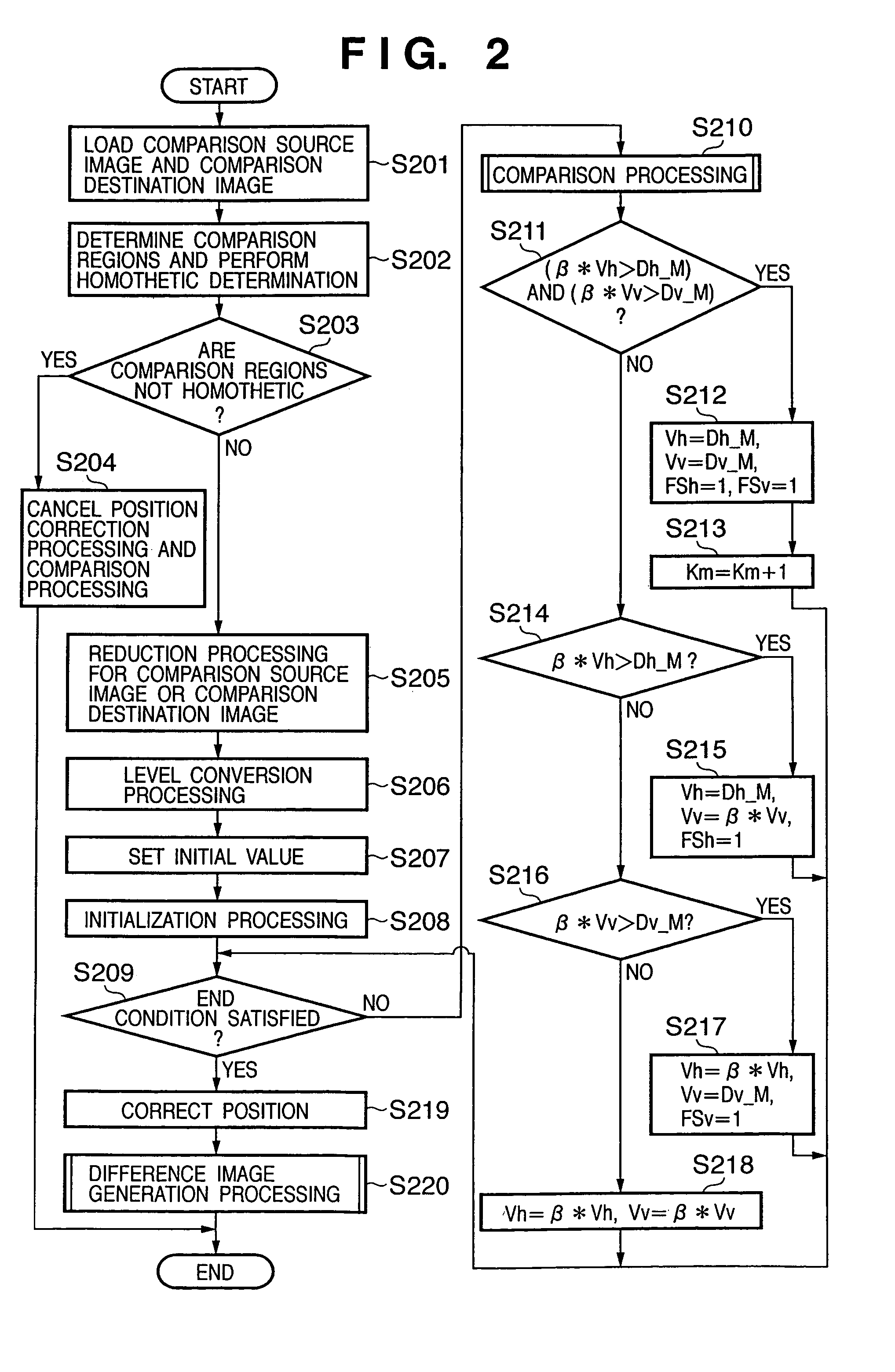
[0084]In the first embodiment, image data scanned in copying an original is stored in a storage device. Processing (comparison processing for details of image data) of searching image data scanned in copying an original having an annotation, stain, or the like for corresponding image data of the original is executed to output the searched image data. The first embodiment will be described by exemplifying this arrangement.

[0085]With this arrangement, an original free from any annotation or stain can be obtained as a copy of the original having an annotation or stain.

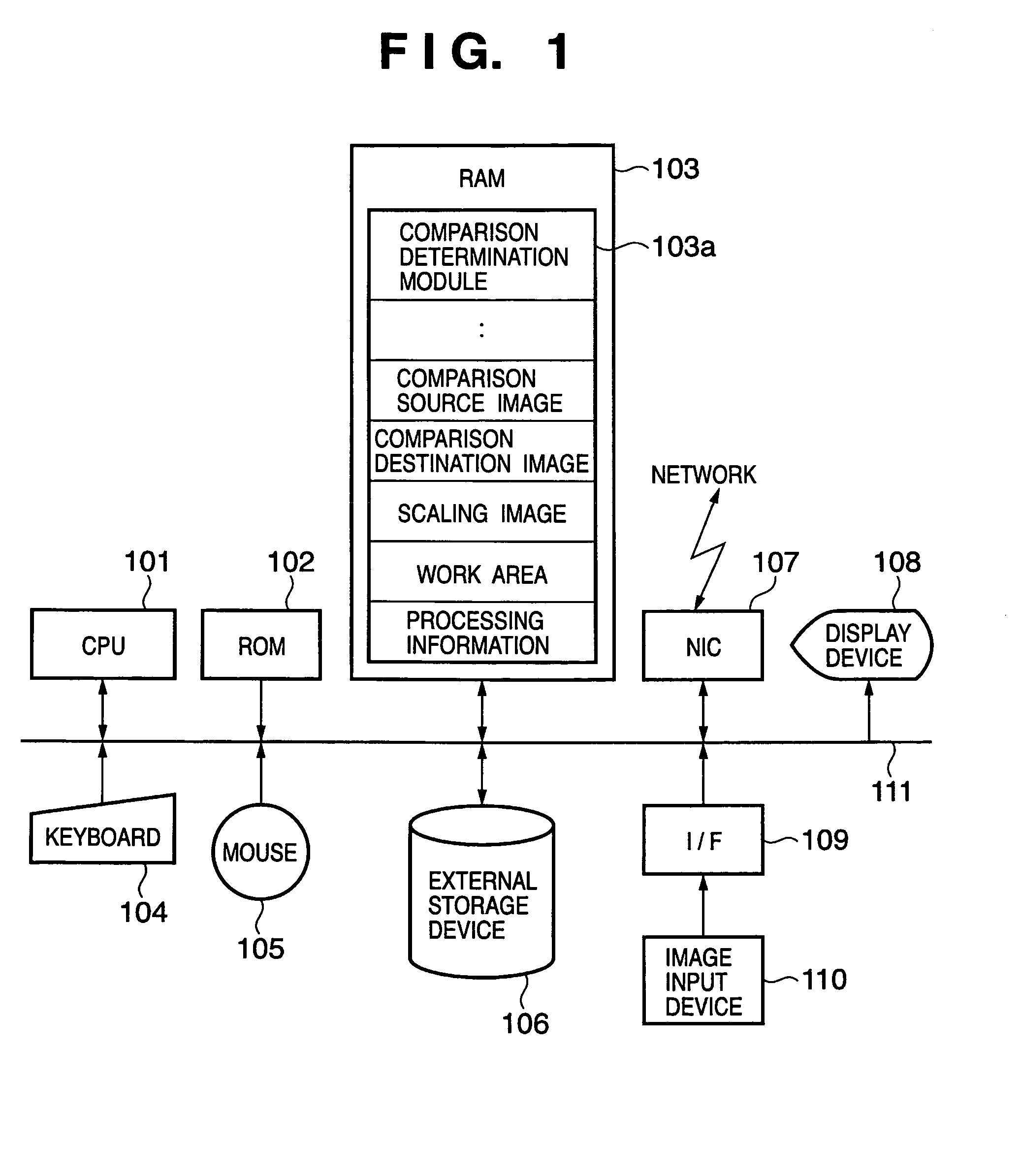
[0086]FIG. 1 is a view showing an example of the arrangement of an image processing apparatus according to the first embodiment of the present invention.

[0087]In FIG. 1, reference numeral 101 denotes a CPU which executes various arithmetic and control operations in image processing (or image search processing) according to the first embodiment. Reference numeral 102 denotes a ROM which stores various permanent data and a ...

second embodiment

[0271]The second embodiment is an application of the first embodiment. The second embodiment will describe an arrangement in which, if the comparison region candidates of a comparison source image and comparison destination image are homothetic in step S203 of FIG. 2, comparison region optimization processing (step S203a) as shown in FIG. 16 is executed.

[0272]After processing in step S203, the comparison region size of the image β out of the images α and β is corrected. At this stage, the coordinates of the comparison region in the circumscribed rectangle of an object are not determined.

[0273]This is because an image to be processed has an annotation, stain, or the like and the circumscribed rectangle of the object becomes large, as shown in FIG. 17.

[0274]In the second embodiment, as shown in FIG. 16, optimization processing of optimizing the coordinates of the comparison region is executed in step S203a, as shown in FIG. 16. This processing can safely absorb an error in an image to...


PUM


Abstract

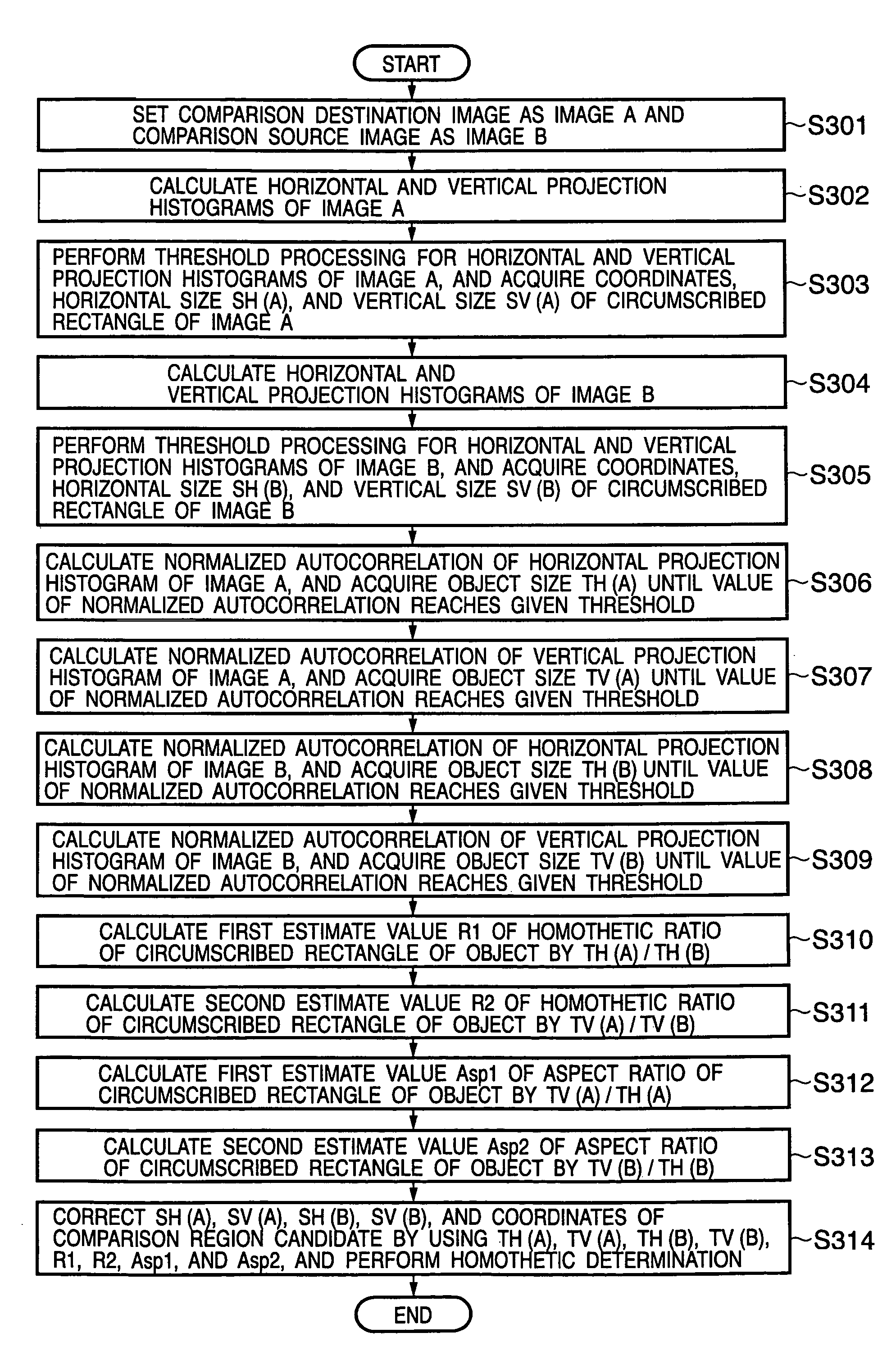
The horizontal and vertical projection histograms of an image to be processed are calculated. The autocorrelation values of the calculated horizontal and vertical projection histograms are calculated, and horizontal and vertical object sizes until the autocorrelation values decrease to predetermined thresholds are calculated. The aspect ratio estimate value of the circumscribed rectangle of an object serving as a comparison region candidate in the image to be processed is calculated on the basis of the calculation results. The comparison region candidate is corrected on the basis of the aspect ratio estimate value, determining a final comparison region.

Description

FIELD OF THE INVENTION[0001]The present invention relates to an image processing apparatus which executes image processing for determining a comparison region used to perform similarity comparison between a comparison source image and a comparison destination image, a control method therefor, and a program.BACKGROUND OF THE INVENTION[0002]As a conventional technique of calculating the homothetic ratio of two images, a technique disclosed in Japanese Patent Laid-Open No. 2003-248827 is known. In Japanese Patent Laid-Open No. 2003-248827, the homothety between a reference image and a check image is calculated to perform similarity collation (similarity comparison) between them. At this time, both the homothetic ratio and the translation amount of a comparison region between the projection waveforms of the reference image are calculated. Homothetic transformation and position correction are performed on the basis of the homothetic ratio and translation amount to achieve a detailed comp...

Claims


Application Information

Patent Timeline
Patent Type & Authority Patents(United States)
IPC IPC(8): G06K9/00G06K9/32G06K9/64
CPCG06K9/4647G06T7/0024G06T2207/20068G06T2207/20021G06T7/30G06V10/507
Inventor SHIIYAMA, HIROTAKA
Owner CANON KK
Learn More