Method for detecting overlapped function area on a touchpad

a technology of function area and touchpad, which is applied in the field of detection methods of touchpads, can solve the problems of inability to detect the function area corresponding to the corner function area, and inability to detect the function area

Inactive Publication Date: 2010-06-22
ELAN MICROELECTRONICS CORPORATION
View PDF7 Cites 2 Cited by
  • Summary
  • Abstract
  • Description
  • Claims
  • Application Information

AI Technical Summary

Problems solved by technology

However, an indefinite command mistake will be easily resulted without any detection methods of distinguishing the accurate commands from a user when the overlapped function area is touched.
However, the touchpad is installed inside a case slot, and there exists a gap surrounding the touchpad, as shown in FIG. 4.
Thus, when a user touches a corner function area and a finger is placed on the gap between the case and the touchpad, obviously, a function corresponding to the corner function area may be missed because of incomplete or soft touching input.

Method used


Image

  • Method for detecting overlapped function area on a touchpad
  • Method for detecting overlapped function area on a touchpad
  • Method for detecting overlapped function area on a touchpad

Examples


first embodiment

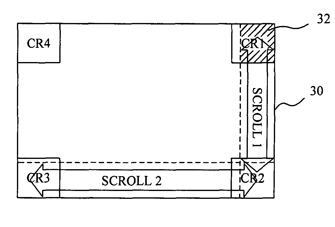
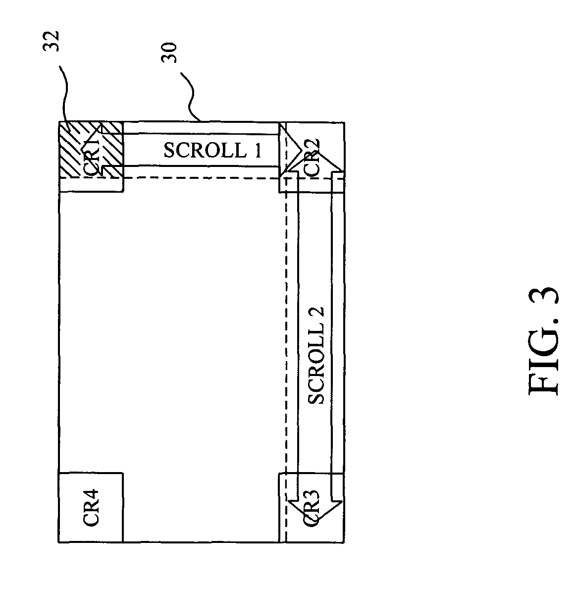
[0022]FIG. 6 is a diagram of the first embodiment of the present invention. Step 40 first determines whether an overlapped area is touched; wherein the overlapped area, for example, is referred to as the overlapped area 32 in FIG. 3, which is overlapped by the corner function area CR1 and the scroll function area SCROLL1. If the result of step 40 is true, step 42 follows and counts a touched duration on the overlapped area, then step 44 follows and determines whether the touched duration is longer than a duration reference. If the result of step 44 is true, step 48 follows and performs a function corresponding to the corner function area CR1; whereas, step 46 follows and performs a function corresponding to the scroll function area SCROLL1.

second embodiment

[0023]FIG. 7 is a diagram of the second embodiment of the present invention. First, step 50 determines whether an overlapped area is touched; wherein the overlapped area, for example, is referred to as the overlapped area 32 in FIG. 3, which is overlapped by the corner function area CR1 and the scroll function area SCROLL1. If the result of the step 50 is true, step 52 follows and measures a touched movement. Step 54 then follows and determines whether the touched movement is larger than a movement reference. If the result of step 54 is true, step 56 follows and performs a function corresponding to the scroll function area SCROLL1; whereas, step 58 follows and counts a touched duration on the overlapped area. Step 60 follows and determines whether the touched duration is longer than a duration reference. If the result of step 60 is true, step 62 follows and performs a function corresponding to the corner function area CR1; whereas, the step is returned to step 56 and then performs a...

third embodiment

[0024]FIG. 8 is a diagram of the third embodiment of the present invention. Step 70 first determines whether an overlapped area is touched; wherein the overlapped area, for example, is referred to as the overlapped area 32 in FIG. 3, which is overlapped by the corner function area CR1 and the scroll function area SCROLL1. Then, step 74 follows and determines whether a terminal touched area is within the corner function area CR1 or the overlapped area 32. If the result of step 74 is true, then step 78 follows and performs a function corresponding to the corner function area CR1; whereas, step 76 follows and performs a function corresponding to the scroll function area SCROLL1.


PUM


Abstract

In a method for detecting overlapped function area on a touchpad with the overlapped function area overlapped by more than two different function areas, when the overlapped function area is touched by an object, a further function can be correctly performed according to touched duration, touched movement, or a terminal touched area pressed onto the touchpad.

Description

FIELD OF THE INVENTION[0001]The present invention is generally related to a detection method for a touchpad and, more particularly, to a method for detecting overlapped function area on a touchpad.BACKGROUND OF THE INVENTION[0002]Touchpad is designed to be an input device. For performing all of its functions such as controlling the movement corresponding to a point, it can be touched or slipped by a finger or a conductive object. Owing to its easy operation, therefore, it is widely applied to electronic products, including portable computer, personal digital assistant (PDA), mobile phone, and etc.[0003]Additionally, for supporting more functions on the limited space, of the touchpad space is improved to comprise more than two operation areas.[0004]FIG. 1 is a diagram of a conventional touchpad 10 having four operation areas placed in the corners respectively. The four operation areas, CR1, CR2, CR3, and CR4, are referred to as “corner function areas”, and generally, they are acted a...

Claims


Application Information

Patent Timeline
Patent Type & Authority Patents(United States)
IPC IPC(8): G09G5/00G06F3/0488
CPCG06F3/04886G06F3/0416G06F3/0485G06F3/04883G06F3/03547
Inventor LII, JIA-YIH
Owner ELAN MICROELECTRONICS CORPORATION
Why Eureka
Try Eureka