
Silicon-based transducer for use in hearing instruments and listening devices

a technology of transducers and hearing instruments, applied in the direction of electric transducers, deaf-aid sets, electrical equipment, etc., can solve the problems of affecting the variation of uniformity and reliability of hearing instruments, and the time-consuming and labor-intensive process of precision-machined electret condenser microphones (ecms). to achieve the effect of increasing the overall signal-to-noise ratio

Inactive Publication Date: 2006-11-28
TDK CORPARATION
View PDF44 Cites 216 Cited by
  • Summary
  • Abstract
  • Description
  • Claims
  • Application Information

AI Technical Summary

Benefits of technology

The present invention is about a hearing instrument that includes a housing, a manually movable structure, and a silicon-based transducer assembly. The transducer assembly includes an ASIC that includes various components such as an A / D converter, D / A converter, DSP, amplifier, preamplifier, voltage stabilizer, charge pump, impedance correction circuit, oscillator, filter, or wireless interface. The hearing instrument also includes at least one silicon-based microphone. The manually movable structure can be an access door, rotatable dial, switch, touch pad, flex-print or printed circuit board. The invention also includes an array of silicon-based microphones that can improve the signal-to-noise ratio, achieve directionality, or provide adaptive beam steering. The patent text is not meant to represent each embodiment or every aspect of the invention.

Problems solved by technology

Fabrication of precision-machined electret condenser microphones (ECMs) is a relatively time- and labor-intensive process, and variations in uniformity and reliability pose challenges relative to the design and performance of microphones or transducer assemblies.
The use of wires to connect components together inside a hearing instrument poses further challenges.
Connecting wires is a labor-intensive process, and they are susceptible to electromagnetic interference which can adversely affect performance.
Moreover, each additional ECM consumes more space, which poses yet additional design challenges.

Method used


Image

  • Silicon-based transducer for use in hearing instruments and listening devices
  • Silicon-based transducer for use in hearing instruments and listening devices
  • Silicon-based transducer for use in hearing instruments and listening devices

Examples


Embodiment Construction

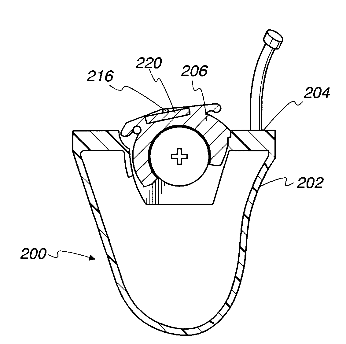
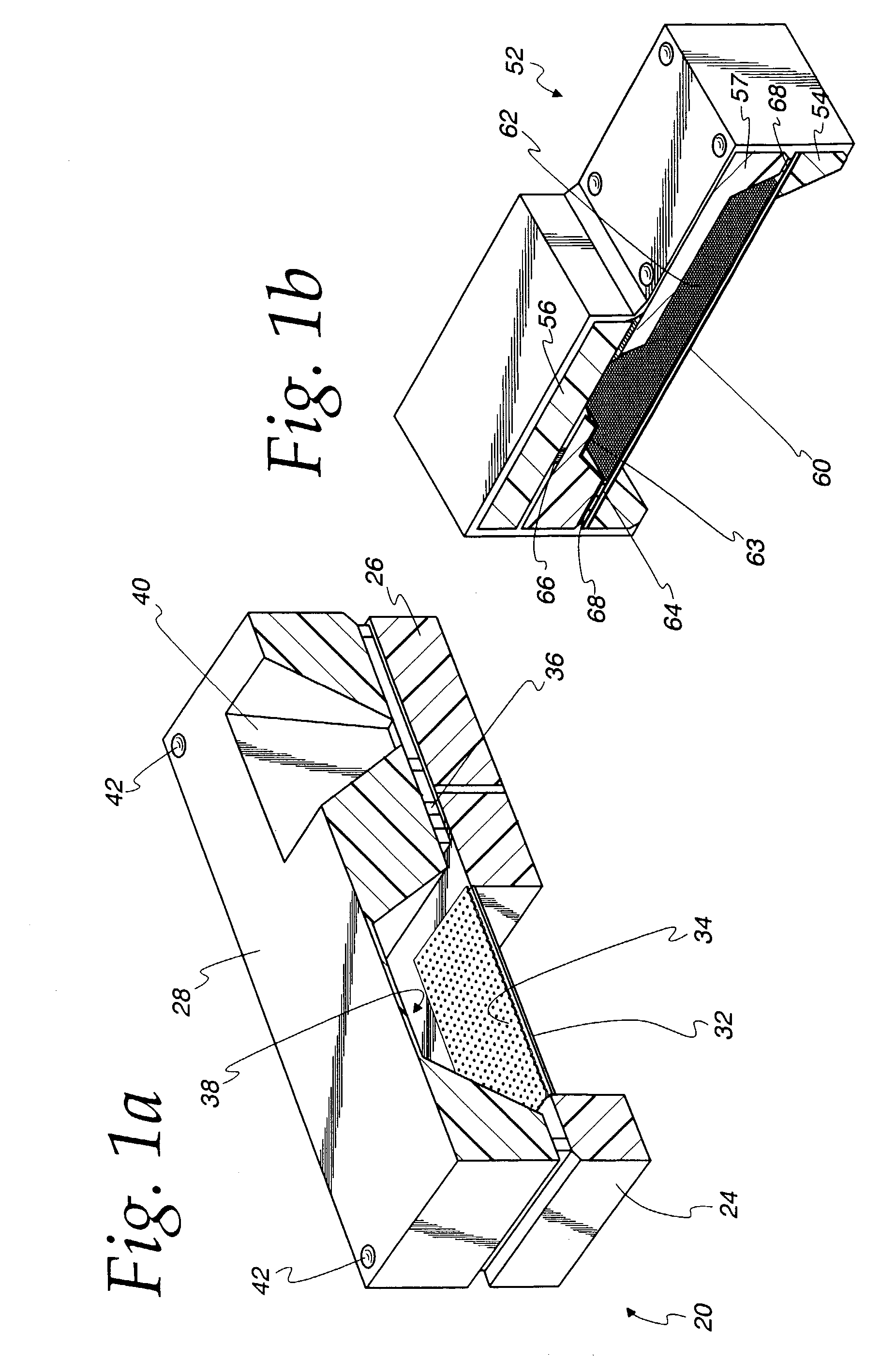
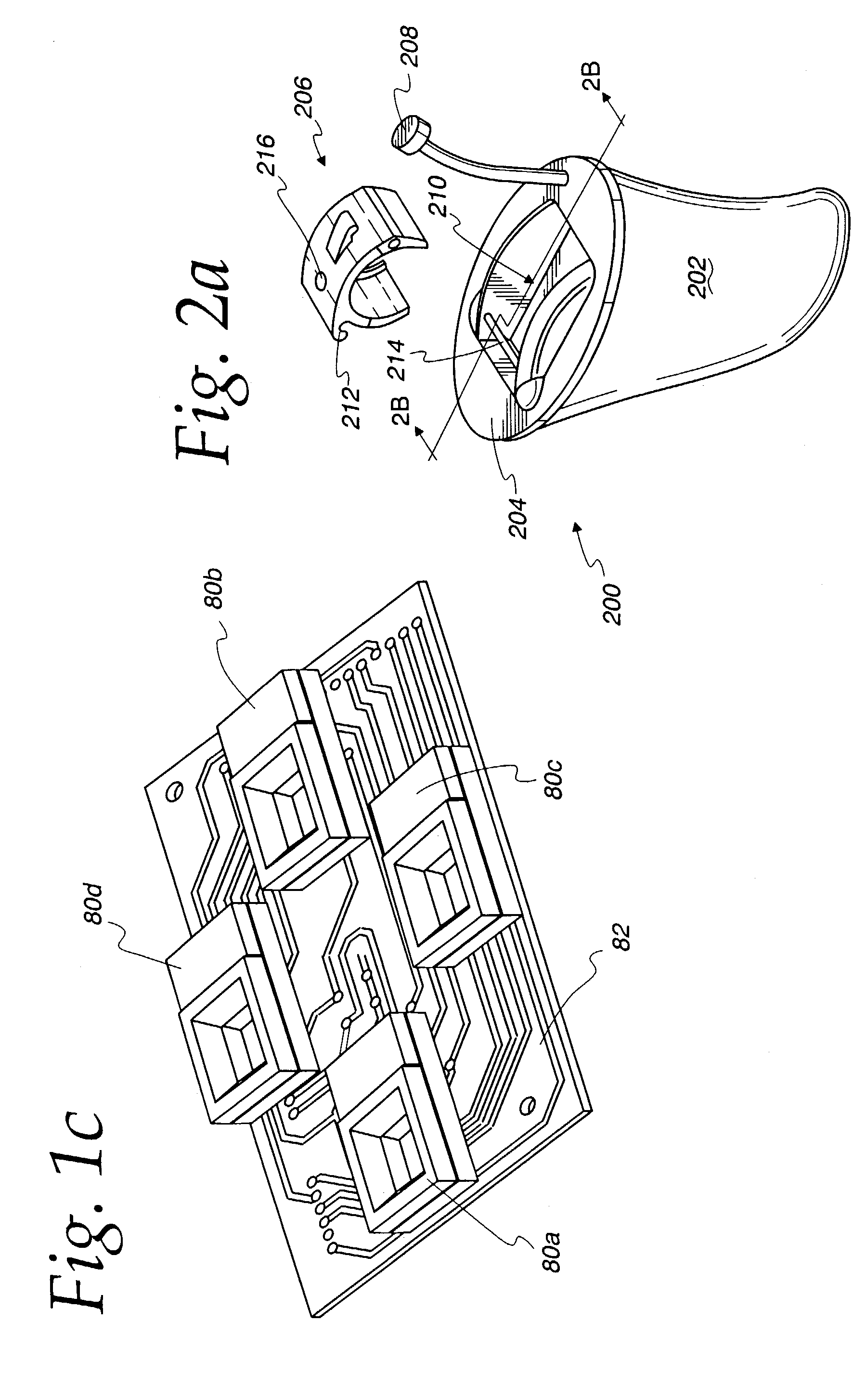
[0031]FIG. 1A is a cutaway perspective view of a silicon-based transducer assembly 20 which generally includes a transducer chip 24 coplanar with an integrated circuit (IC) chip 26, an intermediate chip 28 disposed adjacent the transducer chip 24 and the IC chip 26. The transducer chip 24 includes a diaphragm 32 and backplate 34, which may be placed on either side of the diaphragm 32. A seal ring 36 surrounds the diaphragm 32 and backplate 34 to form a backchamber 38. Redistribution circuits on the intermediate chip 28 electrically connect the diaphragm 32 and backplate 34 to the IC chip 26. Pads 42 or solder bumps are disposed on an exposed surface of the intermediate chip 28 as shown for connection to external components such as a battery (not shown), an amplifier (not shown) or DSP (not shown), a wireless interface (not shown) or a receiver (not shown). The pads 42 are connected to the transducer chip and / or the ASIC via feedthroughs running through the feedthrough opening 40. Fe...


PUM


Abstract

A silicon-based transducer assembly coupled to a movable structure in a hearing instrument. The transducer assembly includes at least one microphone chip and an ASIC having multiple integrated components such as any combination of a DSP, an A / D converter, an amplifier, a filter, or a wireless interface. The movable structure may be a battery access door, a volume dial, a switch, or a touch pad. A protection strip can be disposed across the battery access door to prevent debris from clogging the silicon-based transducer assembly. The transducer assembly may also include an array of microphone chips to achieve adaptive beam steering or directionality. When equipped with a wireless interface, the hearing instrument wirelessly communicates with another hearing instrument or with a network.

Description

FIELD OF THE INVENTION[0001]The present invention relates generally to silicon-based transducers, and more particularly, to silicon-based transducers for use in hearing instruments and listening devices.BACKGROUND OF THE INVENTION[0002]A hearing instrument usually consists of a shell which is shaped to fit inconspicuously into an ear canal or behind an ear. The shell generally accommodates a microphone, a receiver (speaker), an amplifier or a DSP, and a battery. The microphone is typically of the electret condenser type, and the DSP or amplifier is ordinarily a separate component which must be hardwired to the other components of the hearing instrument. Producing a hearing instrument requires balancing several competing considerations including the volume and shape of the shell, cost, and the desired functions to be incorporated into the hearing instrument.[0003]Fabrication of precision-machined electret condenser microphones (ECMs) is a relatively time- and labor-intensive process,...

Claims


Application Information

Patent Timeline
Patent Type & Authority Patents(United States)
IPC IPC(8): H04R25/00H04R19/00
CPCH04R19/005H04R25/604H04R25/48H04R25/556H04R2225/61H04R25/407B33Y80/00H04R25/603
Inventor MULLENBORN, MATTHIASVAN HALTEREN, AART Z.
Owner TDK CORPARATION
Learn More