Three-dimensional imaging system

a three-dimensional imaging and imaging system technology, applied in the field of three-dimensional imaging systems, can solve the problems of high cost, large and heavy devices, and many technical problems involved, and achieve the effect of reducing the risk of accidents, and reducing the cost of equipmen

Active Publication Date: 2010-06-22
STEREO DISPLAY
View PDF87 Cites 9 Cited by
  • Summary
  • Abstract
  • Description
  • Claims
  • Application Information

AI Technical Summary

Benefits of technology

[0011]An objective of the invention is to provide a real-time three-dimensional imaging system that can provide an all-in-focus image and depth information for each pixel of the all-in-focus image.
[0013]Another objective of the invention is to provide a three-dimensional imaging system that can compensate for various optical distortions or aberrations.
[0016]The MMAL has many advantages over conventional variable focus lenses including a very fast response time because each micromirror has a tiny mass, a large focal length variation because large numerical aperture variations can be achieved by increasing the maximum rotational angle of the micromirrors, a high optical focusing efficiency, a large aperture without losing optical performance, low cost because of the advantage of mass productivity of microelectronics manufacturing technology, capability of compensating for phase errors introduced by the medium between the object and the image and / or correcting the defects of the lens system that cause its image to deviate from the rules of paraxial imagery, simpler focusing mechanism, and low power consumption when electrostatic actuation is used to control it.
[0021]The three-dimensional imaging system of the present invention compensates for aberrations using the MMAL. Since the MMAL is an adaptive optical component, the MMAL compensates for phase errors of light introduced by the medium between an object and its image and / or corrects the defects of the three-dimensional imaging system that may cause the image to deviate from the rules of paraxial imagery by controlling individual micromirrors in the MMAL.
[0031]In summary, the three-dimensional imaging system of the present invention has the following advantages: (1) the system can make a real-time three-dimensional image because the MMAL has a fast focusing time; (2) the system has a large range of depth because the MMAL has a large focal length variation; (3) the system has a high optical efficiency; (4) the system can have high depth resolution by controlling the focal length of the MMAL in the small scale; (5) the cost is inexpensive because the MMAL is inexpensive; (6) the system can compensate for aberrations of the imaging system; (7) the system is very simple because there is no macroscopic mechanical displacement or deformation of the lens system; (8) the system is compact; and (9) the system requires small power consumption when the MMAL is actuated by electrostatic force.

Problems solved by technology

These devices, however, tend to be large and heavy, and come at high cost due to multiple camera systems and their optical axis separation requirement.
Also, when stereoscopic images are displayed for three-dimensional viewing, many technical problems can be arisen involved with arbitrary distribution of the viewer's position, watching by multiple viewers, binocular disparity due to deviations in the distance between the two eyes, vergence, fatigue accumulation in the eye, accommodation, the relative position change of the three-dimensional image due to viewer's movement, etc.
The holographic imaging system requires expensive and high power consuming coherent light source such as laser and the near darkroom conditions for imaging.
Therefore, the holographic imaging system is not applicable to portable imaging devices as well as may cause some safety concerns using in the public area.
The confocal system can provide a high resolution three-dimensional image with a single camera system, but most of illuminating light is wasted and causes noise problem.
To overcome this, U.S. Pat. No. 6,749,346 to Dickensheets and U.S. Pat. No. 6,563,105 to Seibel use a single optical fiber to scan and collect reflected light, but point by point scanning can lead to a slow image refresh rate.
Conventional motorized optics has a slow response time and complex driving mechanisms to control the relative position of the lenses.
Therefore, it is difficult to use in the real-time imaging system and miniaturize the imaging system.

Method used


Image

  • Three-dimensional imaging system
  • Three-dimensional imaging system
  • Three-dimensional imaging system

Examples


Embodiment Construction

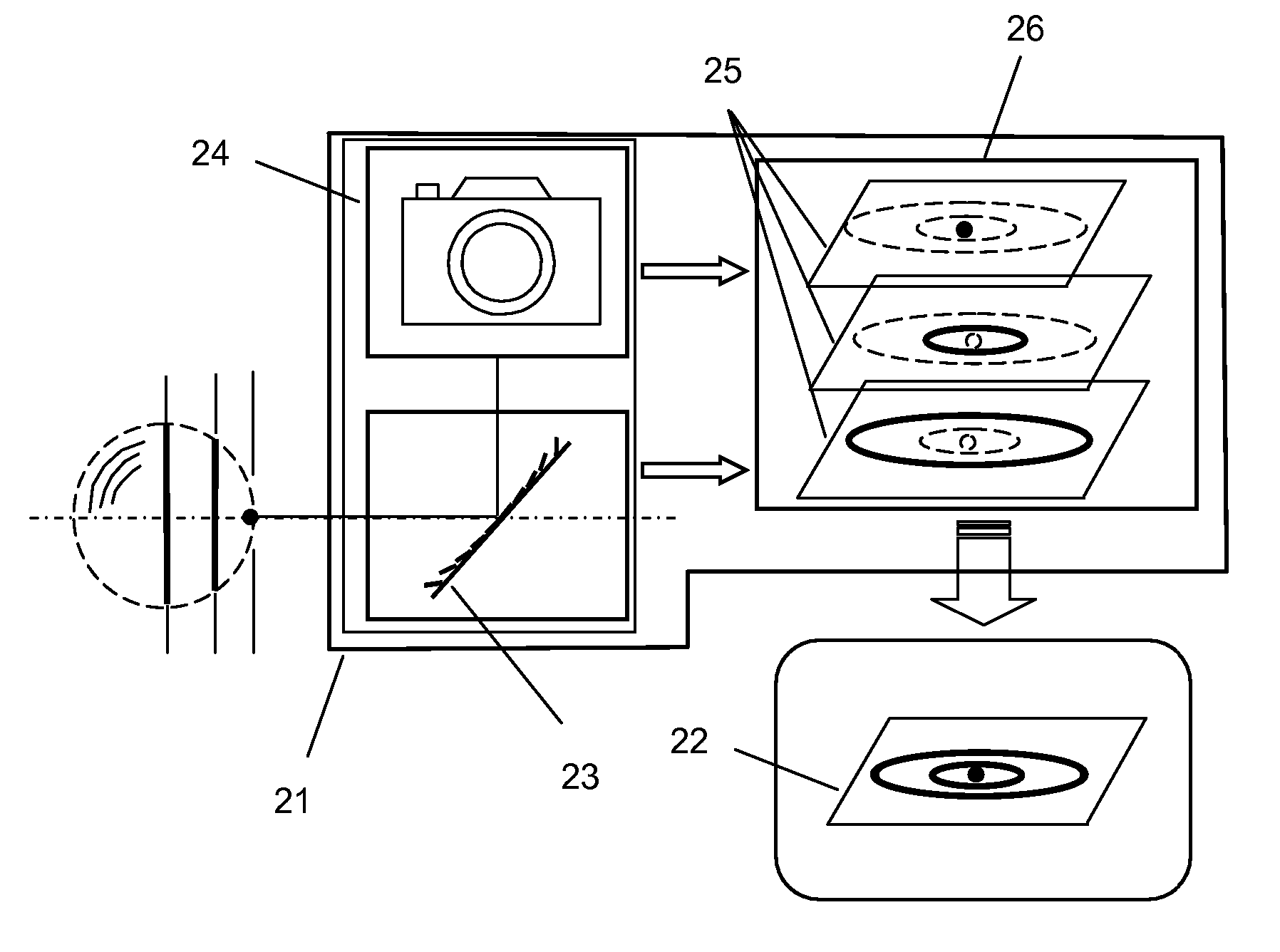
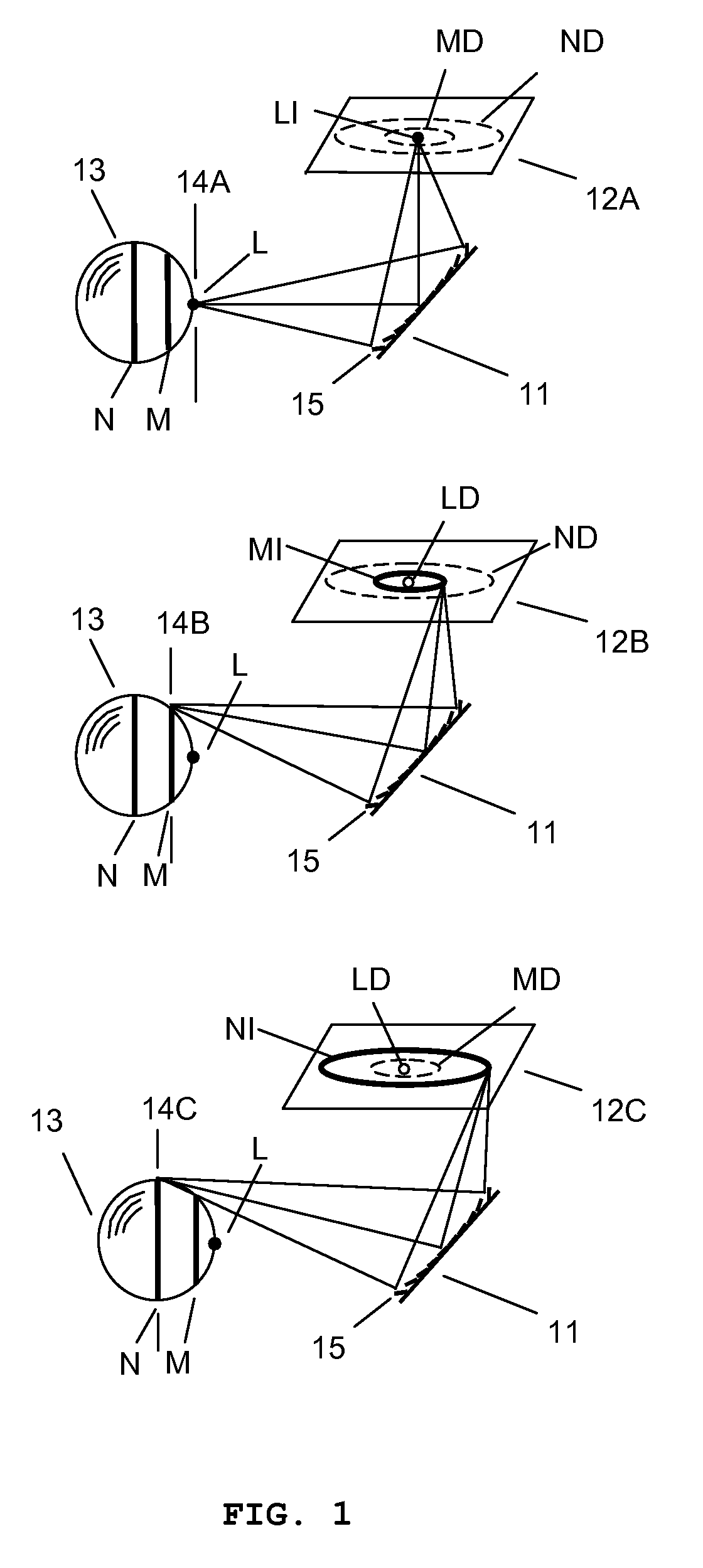
[0043]FIG. 1 shows how a three-dimensional image is obtained from two-dimensional images captured by a variable focal length MMAL 11. Two-dimensional images 12A, 12B, and 12C are captured by changing the focal length of the MMAL 11. Captured two-dimensional images 12A, 12B, and 12C have different in-focus pixels because the in-focus plane in an object 13 is varied as the focal length of the MMAL 11 is varied. The captured two-dimensional image 12A with the first focal length has an in-focus image LI which is the image of the portion L of the object 13. The portion L of the object 13 lies on the in-focus plane 14A while images MD, ND of portion M, N of the object 13 are defocused. Therefore, the image processing unit can extract the in-focus pixels LI from the captured two-dimensional images 12A and generate a depthwise image, which contains only in-focus pixels. The distance between the in-focus plane 14A in the object and the imaging system can be estimated by using known imaging s...


PUM


Abstract

A new three-dimensional imaging system has been needed to overcome the problems of the prior arts using conventional variable focal length lenses, which have slow response time, small focal length variation, and low focusing efficiency, and require a complex mechanism to control it. The three-dimensional imaging system of the present invention uses the variable focal length micromirror array lens. Since the micromirror array lens has many advantages such as very fast response time, large focal length variation, high optical focusing efficiency, large size aperture, low cost, simple mechanism, and so on, the three-dimensional imaging system can get a real-time three-dimensional image with large depth range and high depth resolution.

Description

REFERENCE TO RELATED APPLICATIONS[0001]This application is a continuation-in-part of, and claims priority to U.S. patent application Ser. No. 10 / 822,414 filed Apr. 12, 2004, U.S. patent application Ser. No. 10 / 855,715 filed May 27, 2004, U.S. patent application Ser. No. 10 / 872,241 filed Jun. 18, 2004, U.S. patent application Ser. No. 10 / 893,039 filed Jul. 16, 2004, U.S. patent application Ser. No. 10 / 896,146 filed Jul. 21, 2004, U.S. patent application Ser. No. 10 / 979,612 filed Nov. 2, 2004, U.S. patent application Ser. No. 10 / 983,353 filed Nov. 8, 2004, U.S. patent application Ser. No. 11 / 072,597 filed Mar. 4, 2005, U.S. patent application Ser. No. 11 / 076,616 filed Mar. 10, 2005, U.S. patent application Ser. No. 11 / 191,886 filed Jul. 28, 2005, U.S. patent application Ser. No. 11 / 208,115 filed Aug. 19, 2005, U.S. patent application Ser. No. 11 / 218,814 filed Sep. 2, 2005, U.S. patent application Ser. No. 11 / 286,971 filed Nov. 23, 2005, U.S. patent application Ser. No. 11 / 294,944 file...

Claims


Application Information

Patent Timeline
Patent Type & Authority Patents(United States)
IPC IPC(8): G02B27/10
CPCG02B26/0833G02B15/00
Inventor CHO, GYOUNG ILKIM, HYE YOUNGSOHN, JIN YOUNGSEO, CHEONG SOO
Owner STEREO DISPLAY
Why Eureka
Try Eureka