X-ray imaging device

a technology of x-ray imaging and imaging device, which is applied in the direction of instruments, diaphragms, and radiation diagnostic devices, etc., can solve the problems of high radiation dose irradiated to an examinee, and large area of x-ray sensor

Active Publication Date: 2019-09-10
VA TECHNOLOGIE +1
View PDF28 Cites 4 Cited by
  • Summary
  • Abstract
  • Description
  • Claims
  • Application Information

AI Technical Summary

Benefits of technology

[0021]According to the present invention having the above-described characteristics, it is possible to provide an X-ray imaging device and an X-ray imaging method that can provide an accurate three-dimensional X-ray image of a field of view having a desired size and shape, for example, a field of view having a width more than twice a width of a sensor, by using a narrow-width sensor and low-dose X-ray exposure compared to a conventional X-ray CT apparatus including a half beam method.
[0022]Further, it is possible to provide an X-ray imaging device that can expand the field of view or select the same to have a free-form shape by using a single fixed rotating axis without adding or moving a physical rotating axis between an X-ray source and an X-ray sensor, and can even provide a panoramic image.

Problems solved by technology

However, it is problematic in that to obtain the X-ray panoramic image, a multi-axis drive system is required to link the rotational movement with the linear movement of X-ray source and the X-ray sensor.
However, it is problematic in that radiation dose irradiated to an examinee is high to obtain a general X-ray CT image, and an expensive X-ray sensor having a large area is required.
However, regardless of the imaging methods, an area of a sensor for X-ray CT is large.
Further, cost of a general sensor increases dramatically according to an area thereof, so an X-ray CT imaging apparatus is problematic in that a sensor having a large area is required.
Accordingly, the cost thereof increases due to size of the sensor.

Method used


Image

  • X-ray imaging device
  • X-ray imaging device
  • X-ray imaging device

Examples


Embodiment Construction

[0028]Reference will now be made in greater detail to exemplary embodiments of the present invention, an example of which is illustrated in the accompanying drawings. Although preferred embodiments of the present invention have been described for a dental X-ray imaging device, those skilled in the art will appreciate that the present invention can be applied to all X-ray imaging devices, without departing from the scope and spirit of the invention as disclosed in the accompanying claims.

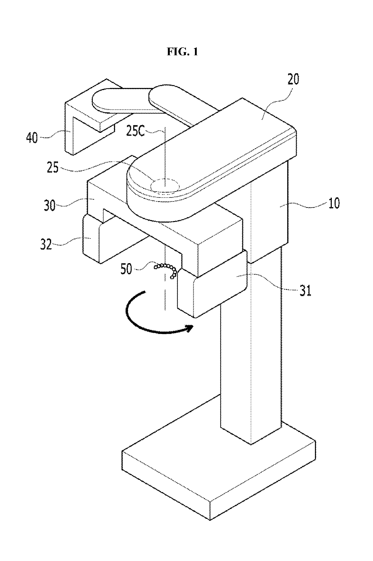
[0029]FIG. 1 is a perspective view showing an X-ray imaging device according to an embodiment of the present invention.

[0030]The X-ray imaging device according to the embodiment includes: a base supported on a floor; a column vertically erected from the base; and an elevation part 10 elevating along the column to correspond to a height of a subject. A rotating arm support 20 is connected to a side of the elevation part 10. The rotating arm support 20 is rotatably provided with a rotating arm 30. The ...


PUM


Abstract

Provided is an X-ray imaging device for radiographing an object. The X-ray imaging device includes a generator configured to emit X-rays, a sensor unit configured to detect the X-rays using at least one sensor, a gantry having the generator and the sensor unit facing with the object therebetween, and a sensor moving part provided in the sensor unit and configured to move the sensor while the gantry rotates about a rotating axis.

Description

CROSS REFERENCE TO RELATED APPLICATIONS[0001]This application is a National Stage Patent Application of PCT International Patent Application No. PCT / KR2015 / 007722 (filed on Jul. 24, 2015) under 35 U.S.C. § 371, which claims priority to Korean Patent Application No. 10-2014-0095717 (filed on Jul. 28, 2014), the teachings of which are incorporated herein in their entireties by reference.TECHNICAL FIELD[0002]The present invention relates generally to an X-ray imaging modality. More particularly, the present invention relates to an X-ray imaging device and an X-ray imaging method that can provide a three-dimensional X-ray image of a field of view having a desired size and shape by using a narrow-width sensor and low-dose X-ray exposure.BACKGROUND ART[0003]X-rays are attenuated according to an X-ray attenuation coefficient, such as photoelectric effect, Compton scattering, and the like, of a substance placed in a path of the X-rays.[0004]X-ray imaging modality is radiography using permea...

Claims


Application Information

Patent Timeline
Patent Type & Authority Patents(United States)
IPC IPC(8): A61B6/14A61B6/00A61B6/03G01T1/161A61B6/06
CPCA61B6/14A61B6/00A61B6/032A61B6/5205G01T1/161A61B6/4435A61B6/06A61B6/4064
Inventor CHOI, SUNGIL
Owner VA TECHNOLOGIE
Why Eureka
Try Eureka