In-vivo sensing system

a sensing system and in-vivo technology, applied in the field of in-vivo sensing, can solve the problems of device trapped in the fold of the walls of the body lumen, slow and unpredictable passive movement of objects through the larger body lumen, etc., to achieve the effect of reducing friction, facilitating change, and widening the field of view that can be captured by the imaging devi

Active Publication Date: 2006-01-05
GIVEN IMAGING LTD
View PDF99 Cites 101 Cited by
  • Summary
  • Abstract
  • Description
  • Claims
  • Application Information

AI Technical Summary

Benefits of technology

[0006] Embodiments of the present invention disclose an in vivo sensing system incorporating a sensing device which may be moved, for example, in a friction-reduced manner. In one embodiment of the invention the sensing device is movably disposed within a typically transparent housing or outer covering such that the orientation of the sensing device may be easily changed in response to substantially small forces, for example, gravitational forces, or electromagnetic torque generating fields, magnetic torque generating fields, or in response to other suitable mechanical or other stimuli. According to one embodiment the sensing system includes a friction reducing mechanism for reducing friction between the sensing device's outer surface and the in vivo housing's internal surface. For example, in one embodiment the sensing device is an imaging device is suspended within a liquid encapsulated within a housing or outer covering or shell. A small external actuation exerted on the imaging device, for example, may thereby be sufficient to alter the orientation of the imaging device thereby changing its line of sight or to permit the rotation of the imaging device within the housing. The field of view that can be captured by the imaging device may be widened. In one embodiment the external actuation may orient the optical axis to any desired direction. Other friction reducing devices, such as bearings may be used.

Problems solved by technology

Other imaging devices do not accommodate directional activators due to constraints in size, availability of power or the necessity for rigid construction of the remote imaging device.
However, passive movement of objects through larger body lumens, such as, the stomach or the large intestine may be slow and unpredictable.
Furthermore, the device may be trapped in a fold of the walls of the body lumen.
In such a position, an illuminating and imaging device may not have a sufficiently wide field of image and / or field of illumination to obtain images suitable for diagnostic purposes.
In these cases monitoring and diagnosing larger body lumens may be not efficient.
One drawback of affixing a sensor such as an imager to an in vivo site is that the direction of the imager and the orientation of the images captured may be limited by the orientation of the imager as it was affixed in vivo.
A single, fixed orientation of an in vivo imager or other sensor may be insufficient to capture data or images of an entire area of interest of an in vivo lumen.

Method used


Image

  • In-vivo sensing system
  • In-vivo sensing system
  • In-vivo sensing system

Examples


Embodiment Construction

[0016] In the following description, various aspects of the present invention will be described. For purposes of explanation, specific configurations and details are set forth in order to provide a thorough understanding of the present invention. However, it will also be apparent to one skilled in the art that the present invention may be practiced without the specific details presented herein. Furthermore, well-known features may be omitted or simplified in order not to obscure the present invention.

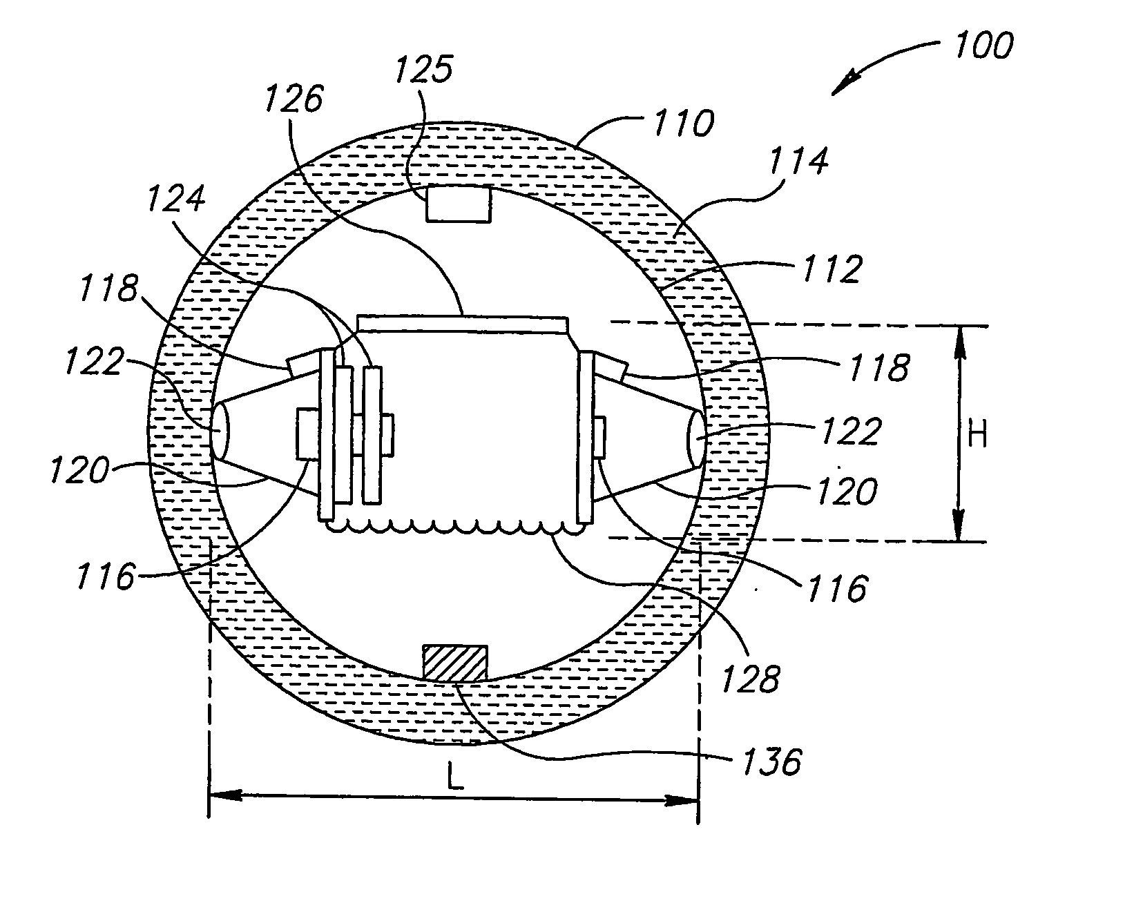
[0017] Reference is made to FIG. 1A which is a simplified conceptual illustration of a sensing system such as an imaging system 100 incorporating a sensing device such as an imaging device 112 suspended in a liquid 114 encapsulated within an outer covering housing 110 constructed and operative in accordance with an embodiment of the invention. The housing 110 may be, for example, spherical, ovoid, or any other suitable shape; the housing 110 may be partially deformable. The imaging dev...


PUM


Abstract

An in-vivo sensing system incorporating a sensing device movably disposed within a housing such that the orientation of the sensing device may be moved or changed in response to substantially small forces. The in-vivo sensing device may bc ingested and may naturally traverse a lumen such as the GI tract or may be anchored at a surgical site. In a preferred embodiment, the in vivo sensing system is an imaging system (100) incorporating a sensing device such as an imaging device (112) suspended in a liquid (114) encapsulated in an covering or housing (110).

Description

FIELD OF THE INVENTION [0001] The present invention relates to the field of in vivo sensing, for example imaging. Specifically, embodiments of the present invention relate to wide or moveable field in vivo imaging or other sensing. BACKGROUND OF THE INVENTION [0002] In vivo sensing can be used for non-invasive diagnostics. Imaging of body lumens typically involves the use of remote imaging devices. Typically, these imaging devices include illuminating capabilities. Certain remote imaging devices can be fitted with directional activators that allow an operator of the remote imaging device to direct the imaging head of the remote imaging device in a particular direction or towards a particular object. Other imaging devices do not accommodate directional activators due to constraints in size, availability of power or the necessity for rigid construction of the remote imaging device. [0003] Swallowable imaging capsules or other suitable devices may be inserted into the gastrointestinal ...

Claims


Application Information

Patent Timeline
Patent Type & Authority Applications(United States)
IPC IPC(8): A61B1/06A61B5/00A61B5/05A61B5/103A61BA61B1/05A61B5/07
CPCA61B1/00016A61B1/00158A61B1/00181A61B1/041A61B5/6882A61B5/03A61B5/073A61B5/14539A61B1/051
Inventor IDDAN, GAVRIEL J.GILAD, ZVIKA
Owner GIVEN IMAGING LTD
Why Eureka
Try Eureka