Gantry positioning apparatus for X-ray imaging

a positioning apparatus and x-ray technology, applied in the field of x-ray imaging, can solve the problems of procedurally cumbersome, limited field of view, and previous attempts to simply not address the true need, and achieve the effect of increasing the field of view of the detector

Inactive Publication Date: 2008-03-04
MEDTRONIC NAVIGATION INC
View PDF99 Cites 103 Cited by
  • Summary
  • Abstract
  • Description
  • Claims
  • Application Information

AI Technical Summary

Benefits of technology

[0014]In still another aspect, the invention relates to gantry imaging systems and methods for enlarging the field of view of an object being imaged which combine a rotation of a radiation source and detector within a gantry with a multi-axis translation of the gantry. The gantry is translated to move the detector closer to the object being imaged, thus increasing the field-of-view. Preferably, the detector is moved tangent to a “virtual circle” within the gantry that is centered on and contains the object to be imaged. As the source and detector rotate through the gantry, the gantry translates in coordination, so that the detector remains tangent to the virtual circle, similar to the motion of a “hula hoop” on the torso of a person.

Problems solved by technology

This is mainly due to the cost, size, and expertise required to operate traditional three-dimensional devices.
Previous attempts simply do not address the true need, which is to maintain a sizable volume while meeting a level of expected image quality.
These C-arm based attempts have a limited field of view, are procedurally cumbersome and have an inherent limit to the image quality.
However, these so-called “mobile CT scanners” are characterized by the elevated dosing level of a traditional fixed CT scanner, they are difficult to maneuver, and they are incapable of performing 2D imaging when that is all that is needed.
In general, the fluoroscopic C-arm attempts meet the criteria of mobility and flexibility, but fall short on image quality and image volume.
The “mobile CT scanner” attempts meet the criteria of image volume and quality, but fail to address the practical issues of usability and cost.
Additionally, state of the art CT scanners are incapable of translating and tilting in the same fashion of mobile fluoroscopy systems.
This is mainly due to the fact that current tomographic scanners are not mobile in a practical manner.
The inability to move a CT scanner with the same degrees of freedom of mobile C-arms has hindered the acceptance and use of mobile three-dimensional imaging.
This has limited the value of three-dimensional computed tomographic imaging to areas mainly as a diagnostic tool in the Radiology Department.

Method used


Image

  • Gantry positioning apparatus for X-ray imaging
  • Gantry positioning apparatus for X-ray imaging
  • Gantry positioning apparatus for X-ray imaging

Examples


Embodiment Construction

[0045]A description of preferred embodiments of the invention follows.

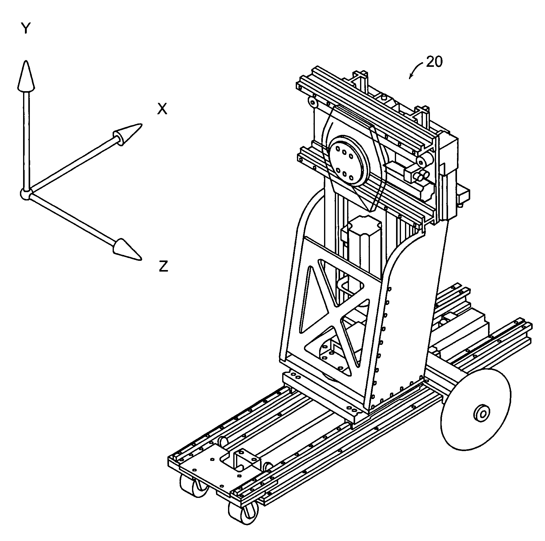
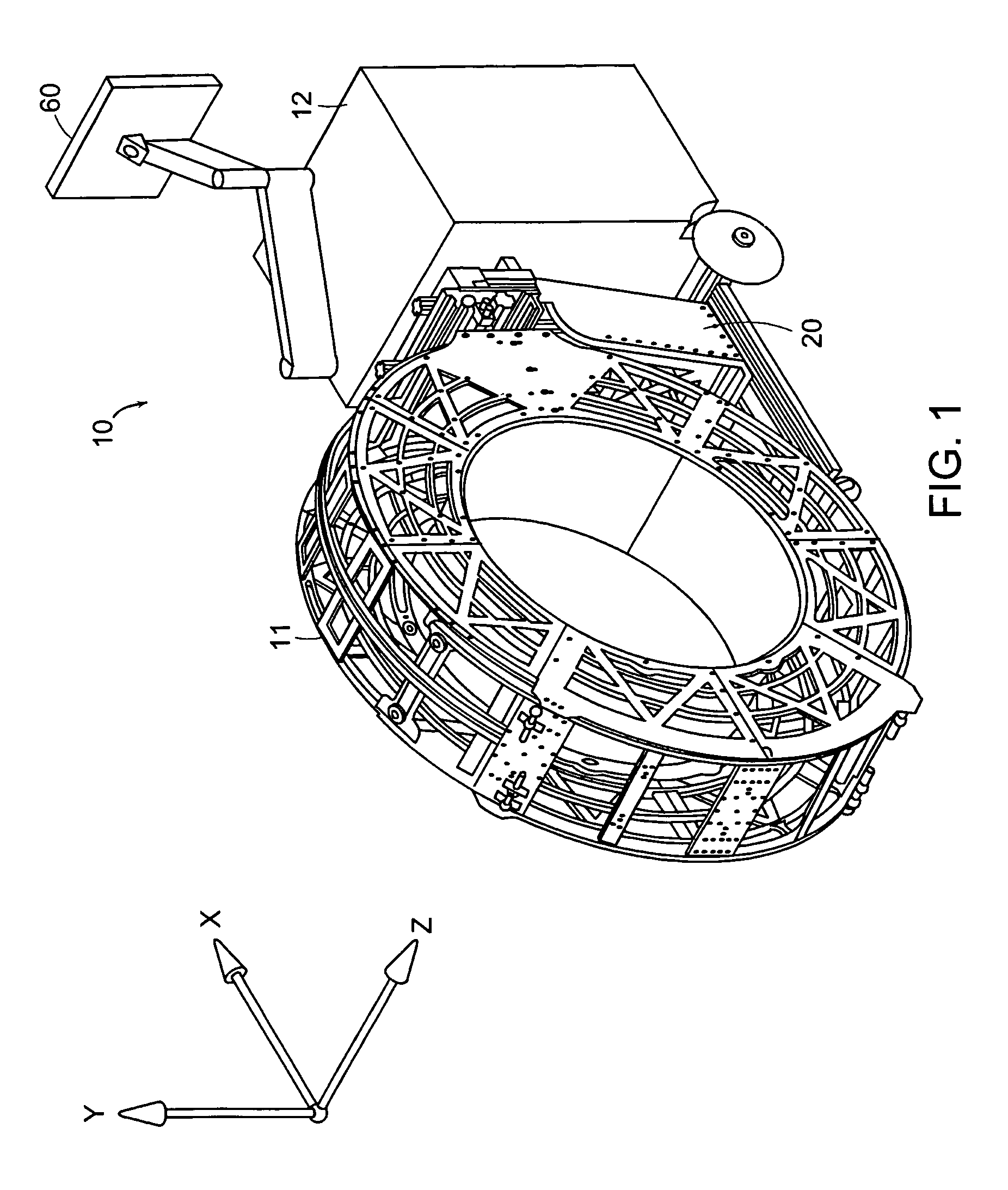
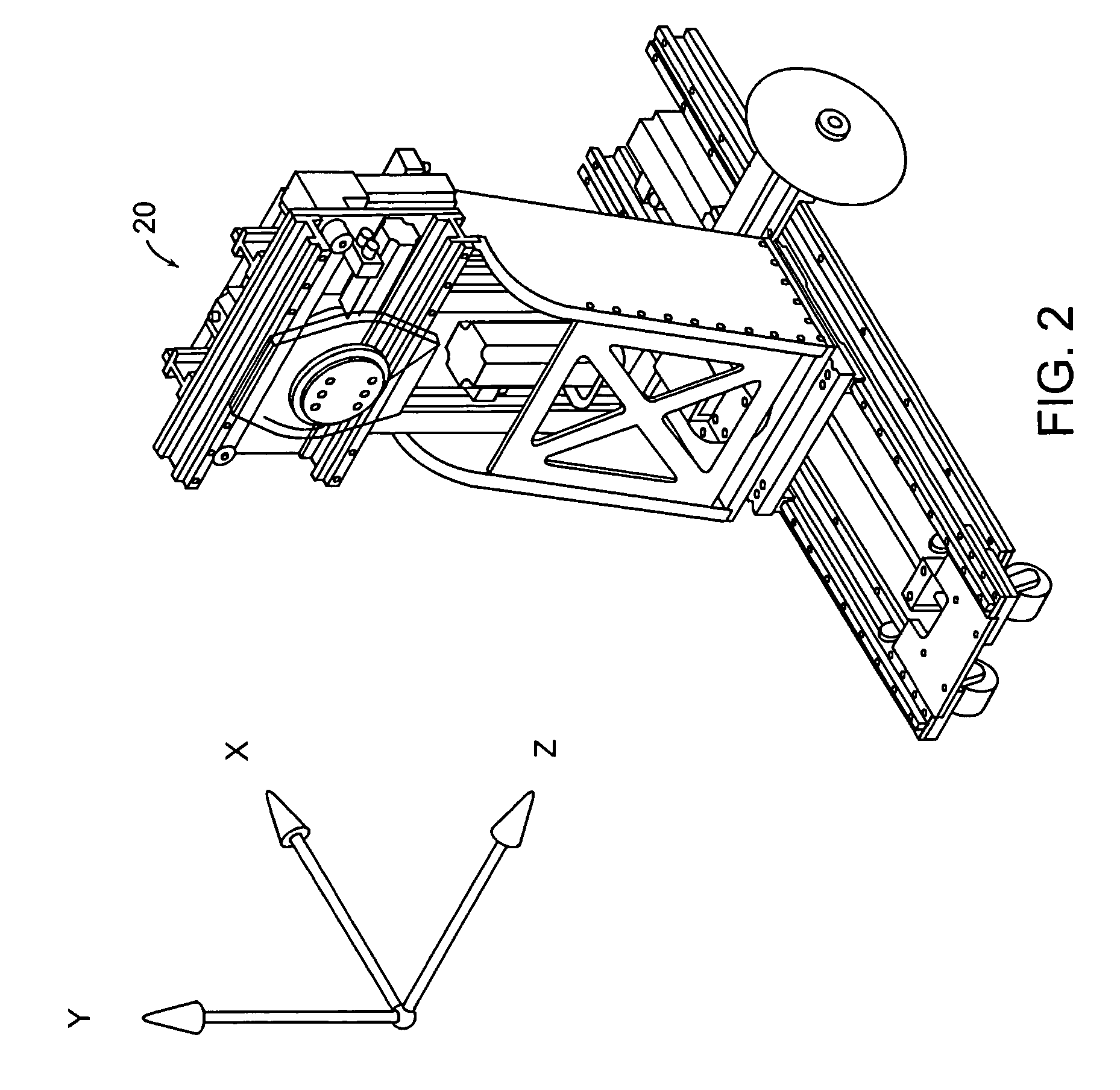
[0046]FIG. 1 is a schematic diagram showing an x-ray scanning system 10 in accordance with one embodiment of the invention. The x-ray scanning system 10 includes a gantry 11 secured to a support structure, which could be a mobile or stationary cart, a patient table, a wall, a floor, or a ceiling. As shown in FIG. 1, the gantry 11 is secured to a mobile cart 12 in a cantilevered fashion via a gantry positioning apparatus 20. As described in further detail below, the gantry positioning apparatus 20 can translate and / or tilt the gantry 11 with respect to the support structure to position the gantry 11 in any number of imaging positions and orientations.

[0047]The mobile cart 12 of FIG. 1 can optionally include a power supply, an x-ray power generator, and a computer system for controlling operation of the x-ray scanning device and for performing image processing, storage of x-ray images, or other data processing funct...


PUM


Abstract

A robotically controlled five degree-of-freedom x-ray gantry positioning apparatus, which is connected to a mobile cart, ceiling, floor, wall, or patient table, is being disclosed. The positioning system can be attached to a cantilevered o-shaped or c-shaped gantry. The positioning system can precisely translate the attached gantry in the three orthogonal axes X-Y-Z and orient the gantry about the X-axis and Y-axis while keeping the center of the gantry fixed, (see FIG. 1). The positioning apparatus provides both iso-centric and non iso-centric “Tilt” and “Wag” rotations of the gantry around the X-axis and Y-axis respectively. The iso-centric “Wag” rotation is a multi-axis combination of two translations and one rotation. Additionally, a field of view larger than that provided by the detector is provided in pure AP (anterior / posterior) and lateral detector positions through additional combinations of multi-axis coordinated motion. Each axis can be manually controlled or motorized with position feedback to allow storage of gantry transformations. Motorized axes enable the gantry to quickly and accurately return to preset gantry positions and orientations.A system and method for enlarging the field of view of the object being imaged combines a rotation of the x-ray source and detector with a multi-axis translation of the gantry.

Description

RELATED APPLICATION[0001]This application claims the benefit of U.S. Provisional Application No. 60 / 405,098, filed Aug. 21, 2002, the entire teachings of which are incorporated herein by reference. This application is related to U.S. application Ser. No. 10 / 459,405, filed on Jun. 11, 2003, the entire teachings of which are incorporated herein by reference.BACKGROUND OF THE INVENTION[0002]Healthcare practices have shown the tremendous value of three-dimensional imaging, mainly as a diagnostic tool in the Radiology Department. Other areas of care, including the operating room, intensive care departments and emergency departments, rely on two-dimensional imaging (fluoroscopy, ultrasound, 2-D mobile X-ray) as the primary means of diagnosis and therapeutic guidance. This is mainly due to the cost, size, and expertise required to operate traditional three-dimensional devices. Moreover, radiologic quality CT scanners have been designed to maximize image quality at the expense of mobility. ...

Claims


Application Information

Patent Timeline
Patent Type & Authority Patents(United States)
IPC IPC(8): H05G1/02A61B6/03A61B6/00
CPCA61B6/032A61B6/4405A61B6/4429A61N5/1081A61B6/4441
Inventor GREGERSON, EUGENE A.GRANT, RICHARD K.JOHNSON, NORBERT J.
Owner MEDTRONIC NAVIGATION INC
Why Eureka
Try Eureka