
Method and apparatus for omnidirectional imaging

a technology of omnidirectional imaging and method, applied in the field of omnidirectional imaging, can solve the problems of inability to generate 3d omnidirectional images, inability to design fish-eye lenses with complicated design, and inability to meet the needs of imaging sensors

Inactive Publication Date: 2001-10-16
TECHNEST HLDG
View PDF10 Cites 105 Cited by
  • Summary
  • Abstract
  • Description
  • Claims
  • Application Information

AI Technical Summary

Benefits of technology

The primary objective of present invention is to provide a set of simple methods and apparatus to obtain simultaneously omnidirectional stereo images without using any moving parts. The field of view of a conventional camera or a light projector can be dramatically increased by employing a reflective mirror properly placed in front of the camera or the projector. A pair of omnidirectional cameras is able to form a unique stereo imaging system that is able to obtain three dimensional images of surrounding scene with 360 degree view angle. A combination of an omnidirectional camera and an omnidirectional structured light projector can also provide a means to obtain quantitative three dimensional measurements of the objects around the camera system. The omnidirectional three dimensional imaging methods and apparatus presented herein may offer unique solutions to many practical systems that need simultaneous 360 degree viewing angle and three dimensional measurement capability.

Problems solved by technology

None of them, however, is able to generate 3D omnidirectional images.
Since sizes of camera lens and the imaging sensor have their practical limitations, the light rays that can be collected by a camera lens and received by the imaging device typically form a corn with very small opening angle.
In general, the wider FOV, the more complicated design the fish-eye lens has.
To obtain a hemispherical FOV, the fish-eye lens must be quite large in dimension, complex in optical design, and hence expensive.
Also, it is very difficult to design a fish-eye lens that ensures single view point constraint, i.e., all incoming principal light rays intersect at a single point to form a fixed viewpoint.
This is indeed a problem with commercial fish-eye lenses, including Nikon's Fisheye-Nikkor 8-mm f / 2.8 lens.
Although the acquired image by fish-eye lenses may prove to be good enough for some visualization applications, the distortion compensation issue has not been resolved, and the high unit-cost remain to be major hurdles for its wide-spread applications.
However the nonlinear property resulted from the semi-spherical optical lens mapping make the resolution along the circular boundary of the image very poor, while the field of view corresponding to the circular boundary of the image usually represents a ground or floor where a high resolution of image is required.
However, issues on seamless integration of multiple images is further complicated by the fact that image produced by each camera has different centers of projection.
The cost for such a system is usually high.
The image processing required by multiple cameras or rotating camera method to obtain a precise information on position and azimuth of an object takes a long time, which is not suitable for real-time battle field modeling and reconnaissance applications.
The first disadvantage of any rotating image system is that it requires the use of moving parts, and precision positioning devices.
A more serious drawback is that such systems lack the capability of simultaneously a acquiring images with wide FOV.
Although such system can acquire precise azimuth information in omnidirectional view, the imaging process is time-consuming and the method is not applicable to real-time problems such as avoiding collision against moving obstacles or monitoring scene with mobile objects.
This restricts the use of rotating systems to static and non-real-time applications.
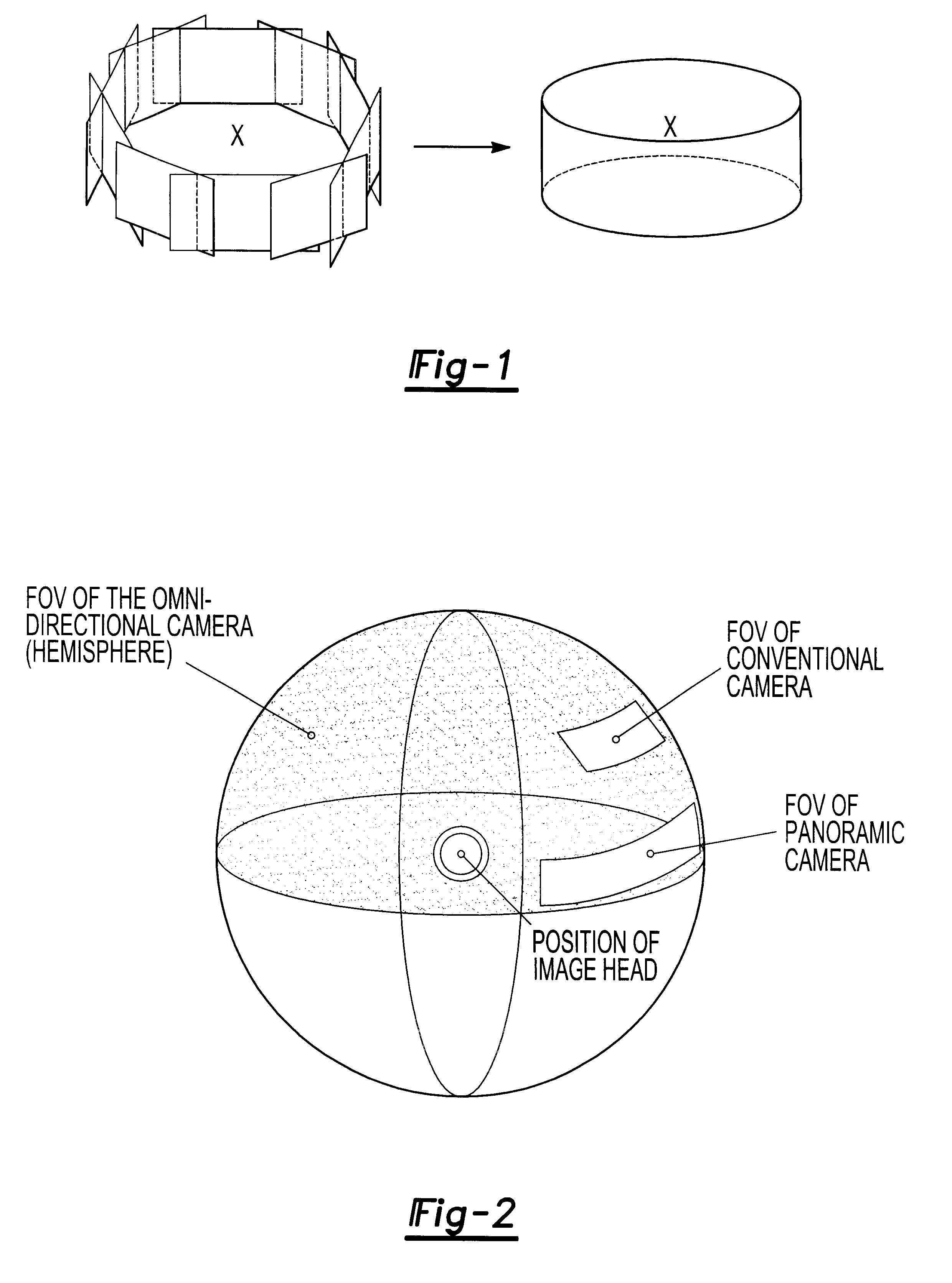
As one can see, a panoramic camera is still not ommidirectional, since it can only provide a wide-angle of FOV at certain time instance, not in all directions.

Method used


Image

  • Method and apparatus for omnidirectional imaging
  • Method and apparatus for omnidirectional imaging
  • Method and apparatus for omnidirectional imaging

Examples


first embodiment

4.4 Omnidirectional Stereo Camera (OSC)

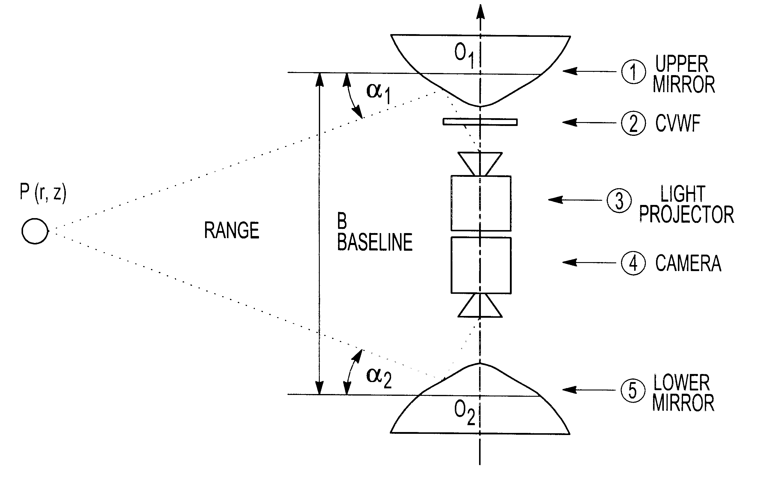
With a pair of the omnidirectional cameras, we can easily construct an omnidirectional stereo camera. FIG. 5 shows a possible configuration of the OSC. Two omni-mirrors are placed face-to-face with optical axes aligned. The virtual imaging centers, O.sub.1 and O.sub.2, are separated by a distance of B, which forms the baseline for the stereo vision.

The triangulation can be carried out directly from omnidirectional images without the need for image conversion. Once a 3D object is detected in the omnidirectional image, the viewing angle .gamma..sub.1 and .gamma..sub.2 can be determined from cameras' geometry. Based on equation (5), the virtual viewing angles of this 3D object, .alpha..sub.1 and .alpha..sub.2, from the virtual viewpoint O.sub.1 and O.sub.2, can be determined. The distance between one of the viewing center and the 3D object in the scene cane be calculated using straight forward triangulation principle: ##EQU5##

where R is the Range...


PUM


Abstract

An omnidirectional imaging system comprising a reflective mirror for viewing object within a hemispherical field of view form a single virtual view point at the local center of said reflective mirror, a projector for projecting a light beam toward said reflective mirror, and a variable wavelength filter optically positioned between said projector and said reflective mirror for generating a pattern having a spatially distributed wavelength spectrum of said reflective mirror, where a generator responsive to the hemispherical image data for generating three-dimensional image.

Description

This invention presents a set of methods and apparatus for omnidirectional stereo imaging. By "omnidirectional imaging system", we mean a system that is able to acquire images with a field-of-view covering entire hemisphere (180 solid space angle), simultaneously without any mechanical moving part. The field of view of a conventional camera or a light projector can be dramatically increased by employing a reflective mirror properly placed in front of the camera or the projector. A pair of omnidirectional cameras is able to form a unique stereo imaging system that is able to obtain three dimensional images of surrounding scene with 360 degree view angle. A combination of an omnidirectional camera and an omnidirectional structured light projector can also provide a means to obtain quantitative three dimensional measurements of the objects around the camera system. The omnidirectional three dimensional imaging methods and apparatus presented herein may offer unique solutions to many pr...

Claims


Application Information

Patent Timeline
IPC IPC(8): H04N5/262H04N5/225H04N13/00H04N13/239
CPCG06T7/0022H04N5/2259H04N5/23238H04N5/2628H04N13/0239G06T7/0057G06T7/0075H04N2013/0088G06T7/97G06T7/521G06T7/593H04N13/239H04N23/58H04N23/698
Inventor GENG, ZHENG JASON
Owner TECHNEST HLDG
Learn More