Brightness enhancement film having a reinforcing structure

a technology of brightness enhancement film and reinforcement structure, which is applied in the field can solve the problems of specific degree of warpage warpage and abrasion of the surface affecting the quality and quantity of brightness enhancement film, etc., and achieves the effect of enhancing a specific degree of hardness of brightness enhancement film and preventing warpage and abrasion of brightness enhancement film

Inactive Publication Date: 2007-09-11
ZHEJIANG JINHUI OPTOELECTRONIC MATERIAL CO LTD
View PDF16 Cites 161 Cited by
  • Summary
  • Abstract
  • Description
  • Claims
  • Application Information

AI Technical Summary

Benefits of technology

[0008]The primary objective of this invention is to provide a brightness enhancement film having a light-refracting microstructure layer and a reinforcing layer at either surface of a substrate. The reinforcing layer can enhance a specific degree of hardness of the brightness enhancement film. Accordingly, the reinforcing layer can prevent warpage and abrasion of the brightness enhancement film.
[0010]Another objective of this invention is to provide the brightness enhancement film having the light-refracting microstructure layer with the light-refracting microstructure selected from prism units, micro-hemispheres, micro cones, micro rippled ridges, meandering microstructure or curved prism units. Accordingly, the light-refracting microstructure can improve light refraction of the brightness enhancement film.
[0011]The brightness enhancement film in accordance with the present invention includes a light-refracting microstructure layer, a substrate and a reinforcing layer. The substrate has a first surface and a second surface opposite thereto. The light-refracting microstructure layer is arranged on the first surface of the substrate and is so configured to vary in curvatures for refracting light. The reinforcing layer is arranged on the second surface of the substrate and is so configured to form a relatively high degree of hardness. Accordingly, the reinforcing layer can prevent warpage and abrasion of the brightness enhancement film.

Problems solved by technology

However, the top surface and the bottom surface disposed on the substrate 11 of the brightness enhancement film 1 are unmatched in structure which may cause a specific degree of warpage of the brightness enhancement film 1 in nature.
This practice unavoidably causes warpage and abrasion of the surfaces of the brightness enhancement films 1, and disadvantageously affects quality and quantity of output of the brightness enhancement films 1.
Even though the brightness enhancement film has the light-diffusing surface at its bottom side, the light-diffusing surface cannot prevent warpage of the brightness enhancement film in nature.
Furthermore, the light-diffusing particles of the brightness enhancement film protrude like raised particles on the light-diffusing surface and, thus, scrape the surface of another brightness enhancement film while piling upon each other.
Also, this practice unavoidably causes warpage and abrasion of the surfaces of the brightness enhancement films, and disadvantageously affects quality and quantity of output of the brightness enhancement films.

Method used


Image

  • Brightness enhancement film having a reinforcing structure
  • Brightness enhancement film having a reinforcing structure
  • Brightness enhancement film having a reinforcing structure

Examples


Embodiment Construction

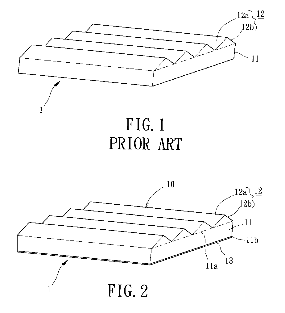
[0023]Referring initially to FIG. 2, a brightness enhancement film 1 having a reinforcing structure in accordance with a first embodiment of the present invention includes a light-refracting microstructure layer 10, a substrate 11 and a reinforcing layer 13. Generally, the substrate 11 has a first surface 11a and a second surface 11b opposite thereto. The substrate 11 is made from a transparent material to permit light to penetrate from the second surface 11b to the first surface 11a, and it further enhances brightness of light.

[0024]Still referring to FIG. 2, the construction of the light-refracting microstructure layer 10 in accordance with the first embodiment of the present invention shall be described in detail. Typically, the light-refracting microstructure layer 10 is deployed on a light emission side of the substrate 11 with respect to a light source (not shown). In the first embodiment, the light-refracting microstructure layer 10 consists of a plurality of prism units 12. ...


PUM

PropertyMeasurementUnit
thicknessaaaaaaaaaa
thicknessaaaaaaaaaa
brightnessaaaaaaaaaa

Abstract

A brightness enhancement film includes a light-refracting microstructure layer, a substrate and a reinforcing layer. The substrate has a first surface and a second surface opposite thereto. The light-refracting microstructure layer is arranged on the first surface of the substrate and is so configured to vary in curvatures for refracting light. The reinforcing layer is arranged on the second surface of the substrate and is so configured to form a relatively high degree of hardness. Accordingly, the reinforcing layer can prevent warpage and abrasion of the brightness enhancement film.

Description

BACKGROUND OF THE INVENTION[0001]1. Field of the Invention[0002]The present invention relates to a brightness enhancement film having a reinforcing structure for use in a liquid crystal display. Particularly, the present invention relates to the brightness enhancement film including a light-refracting microstructure layer and a reinforcing layer at either side thereof. More particularly, the present invention relates to the brightness enhancement film having the reinforcing structure which has a degree of hardness greater than that of a substrate.[0003]2. Description of the Related Art[0004]Referring initially to FIG. 1, U.S. Pat. No. 5,626,800, entitled “Prevention of Groove Tip Deformation in Brightness Enhancement Film,” discloses a brightness enhancement film 1 including a substrate (i.e. base) 11 and a plurality of prism units 12 provided thereon. The prism units 12 are arranged and juxtaposed on a top surface of the substrate 11 in order. Each of the prism units 12 consists of...

Claims


Application Information

Patent Timeline
Patent Type & Authority Patents(United States)
IPC IPC(8): G02B6/10G02B6/34G02F1/1335
CPCG02B5/045G02B6/0053G02B3/0006Y10S385/901
Inventor TANG, SHIH-CHIEH
Owner ZHEJIANG JINHUI OPTOELECTRONIC MATERIAL CO LTD
Why Eureka
Try Eureka